
Carbon-based foam nanocomposite hydrogen storage material

Active Publication Date: 2007-12-20
UNIV OF WASHINGTON +1
View PDF11 Cites 66 Cited by
  • Summary
  • Abstract
  • Description
  • Claims
  • Application Information

AI Technical Summary

Benefits of technology

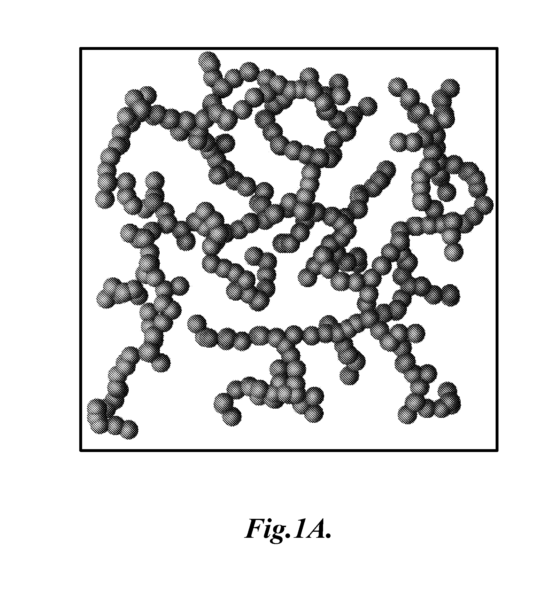
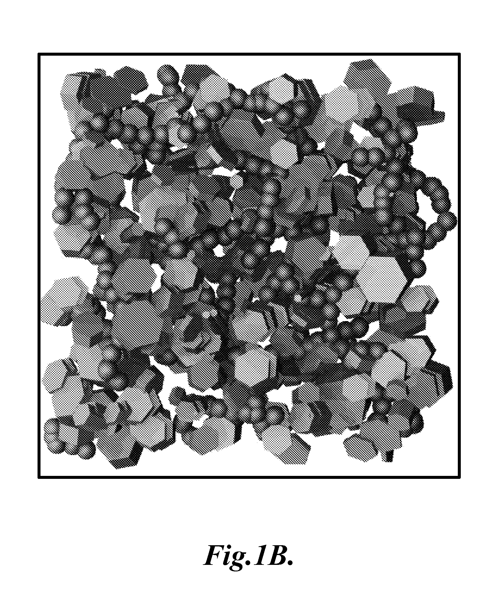
[0005] In one aspect, the present invention provides a composite comprising a carbon-based foam and a solid state hydrogen storage material. In one embodiment, the carbon-based foam is a carbon cryogel. In another embodiment, the carbon-based foam is a carbon aerogel. In another embodiment, the carbon-based foam is a carbon xerogel. The solid state hydrogen storage material is a hydrogen storage material. The solid state hydrogen storage material can be a metal hydride or a chemical hydride. In one embodiment, the metal hydride is magnesium hydride. In one embodiment, the chemical hydride is ammonia borane. In one embodiment, the composite further comprises a catalyst that is effective in lowering the temperature required for release of hydrogen from the composite, for increasing the amount of hydrogen released from the composite at a particular temperature, or for increasing or controlling the rate at which hydrogen is released from the composite. In one embodiment, the composite further comprises surfaces that have been modified to include sulfur groups. The carbon-based foam has a surface area of from about 20 m2 / g to about 3000 m2 / g.

Problems solved by technology

Unfortunately, hydrogen storage systems suitable for automotive and other small-scale industrial or residential applications remain elusive.
Unfortunately these materials have their own problems including poor reversibility, unacceptable reaction kinetics, and inadequate thermal conductivity.

Method used


Image

  • Carbon-based foam nanocomposite hydrogen storage material
  • Carbon-based foam nanocomposite hydrogen storage material
  • Carbon-based foam nanocomposite hydrogen storage material

Examples


example 1

The Preparation of a Representative Magnesium Hydride Carbon Cryogel Composite

[0086] The chemicals utilized in this example are as follows: resorcinol {99+%, Sigma-Aldrich, C6H4(OH)2}, formaldehyde solution {37%—stabilized with methanol (C2H5OH), Fisher Scientific, COH2}, sodium carbonate {99.5%, Sigma-Aldrich, NaCO3}, trifluoroacetic acid {99%, Aldrich, C2HF3O2}, tert-butyl-alcohol (t-butanol) {99.8%, J. T. Baker, (CH3)3COH}, and magnesium hydride {MgH2}. These were used as received without further treatment. Carbon cryogels with resorcinol:catalyst ratio (R / C) held at 50:1 or 200:1, the weight percent solids at 5% (R / W) were fabricated using the method described in Pekala, R W., Journal of Materials Science 24(9):3221-7, 1989, as modified by the method described in Tamon, H., Ishizaka, H., Yamamoto, T., Suzuki T., 379(12): 2049-55, 1999. The molar ratio of resorcinol to formaldehyde was maintained at 1:2 for all sols. The sols were prepared by admixing resorcinol and formaldehyde...

example 2

The Preparation of a Representative Ammonia Borane Carbon Cryogel Composite

[0090] Ammonia borane (AB) AB was added to THF until saturation and then loaded into a carbon cryogel to achieve a 37% by weight AB composite material. AB shows a significant reduction in decomposition temperature. FIG. 9 shows the decomposition peak for bulk AB at about 100° C. While the AB carbon cryogel composite demonstrates the same peak hydrogen release temperature, the hydrogen release begins at a much lower temperature of 50° C., indicating a significant change in the reaction. This is supported by FIG. 10 which shows a change in the thermodynamics as demonstrated by differential scanning calorimetry (DSC) (heating rate of 1° C. / min). FIG. 10 shows an endothermic reaction starting at the same temperature that hydrogen release begins. FIG. 11 also shows a change in the reaction byproducts. AB when dehydrogenated in bulk will release large quantities of borazine. This is not the case for the AB carbon ...

example 3

Metal Catalyst Addition to Carbon-Based Foams

[0091] Carbon-based foams are doped with transition metal catalysts including Ni, Ce, and Zr catalysts. Two sets of sols with R / C:50 and R / C:300 were made and then further separated into four, to which nickel acetate and Ce / Zr acetate were added in small quantities. The nickel acetate was added to each batch at 2.5% of the weight of resorcinol and the equal molar combination of Ce / Zr acetate was added at 3.1% of the weight of resorcinol. The carbon-based foams were then processed according to the standard route (as described above) to create carbon-based cryogels, but were not activated in CO2. The cryogels were characterized by TEM and XRD revealing the presence of the catalysts in the cryogel lattice.


PUM

PropertyMeasurementUnit
Temperatureaaaaaaaaaa

Abstract

A carbon-based foam composite including a carbon-based foam and a solid state hydrogen storage material, methods for making the carbon-based foam composite, and methods for using the carbon-based foam composite. Representative carbon-based foams include cryogels, aerogels, and xerogels. Representative solid state hydrogen storage materials include metal hydrides and chemical hydrides.

Description

CROSS-REFERENCE TO RELATED APPLICATION [0001] This application claims the benefit of U.S. Provisional Application No. 60 / 740,960, filed Nov. 30, 2005, expressly incorporated herein by reference in its entirety.BACKGROUND OF THE INVENTION [0002] It is well recognized that hydrogen fuel generated from renewable power would be a desirable option to continued use of fossil fuels. Hydrogen powered fuel cells are developing rapidly, are more efficient than internal combustion engines, and have only water as an emission. Unfortunately, hydrogen storage systems suitable for automotive and other small-scale industrial or residential applications remain elusive. Solid state hydrogen materials such as metal hydrides or chemical hydride are some of the best potential materials for solving this problem. Unfortunately these materials have their own problems including poor reversibility, unacceptable reaction kinetics, and inadequate thermal conductivity. A cursory review of known hydrides reveals...

Claims


Application Information

Patent Timeline
IPC IPC(8): H01M8/10B01J13/00C08J3/02C01B32/336
CPCB82Y30/00C01B3/0021C01B31/00F17C11/005H01M8/04007Y02E60/50H01M8/04216H01M8/065Y02E60/321Y02E60/325H01M8/04089C01B32/00Y02E60/32B82Y40/00C01B3/00H01M8/04
Inventor FEAVER AARONCAO GUOZHONG
Owner UNIV OF WASHINGTON
Learn More