
Method And System For Production Of Radioisotopes, And Radioisotopes Produced Thereby

a radioisotope and radioisotope technology, applied in chemical to radiation conversion, nuclear elements, nuclear engineering, etc., can solve the problems of irradiation time, high cost, and inability to produce prior art particle accelerators, and achieve the effect of preventing contamination or communication

Inactive Publication Date: 2007-12-27
SOREQ NUCLEAR RES CENT ISRAEL ATOMIC ENERGY COMMISSION
View PDF8 Cites 131 Cited by
  • Summary
  • Abstract
  • Description
  • Claims
  • Application Information

AI Technical Summary

Benefits of technology

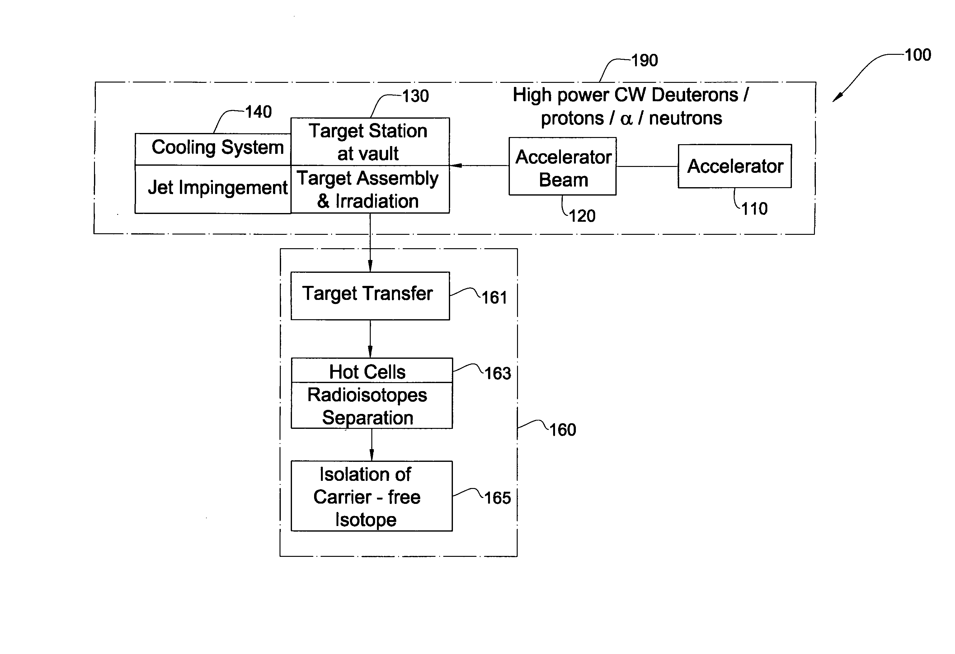
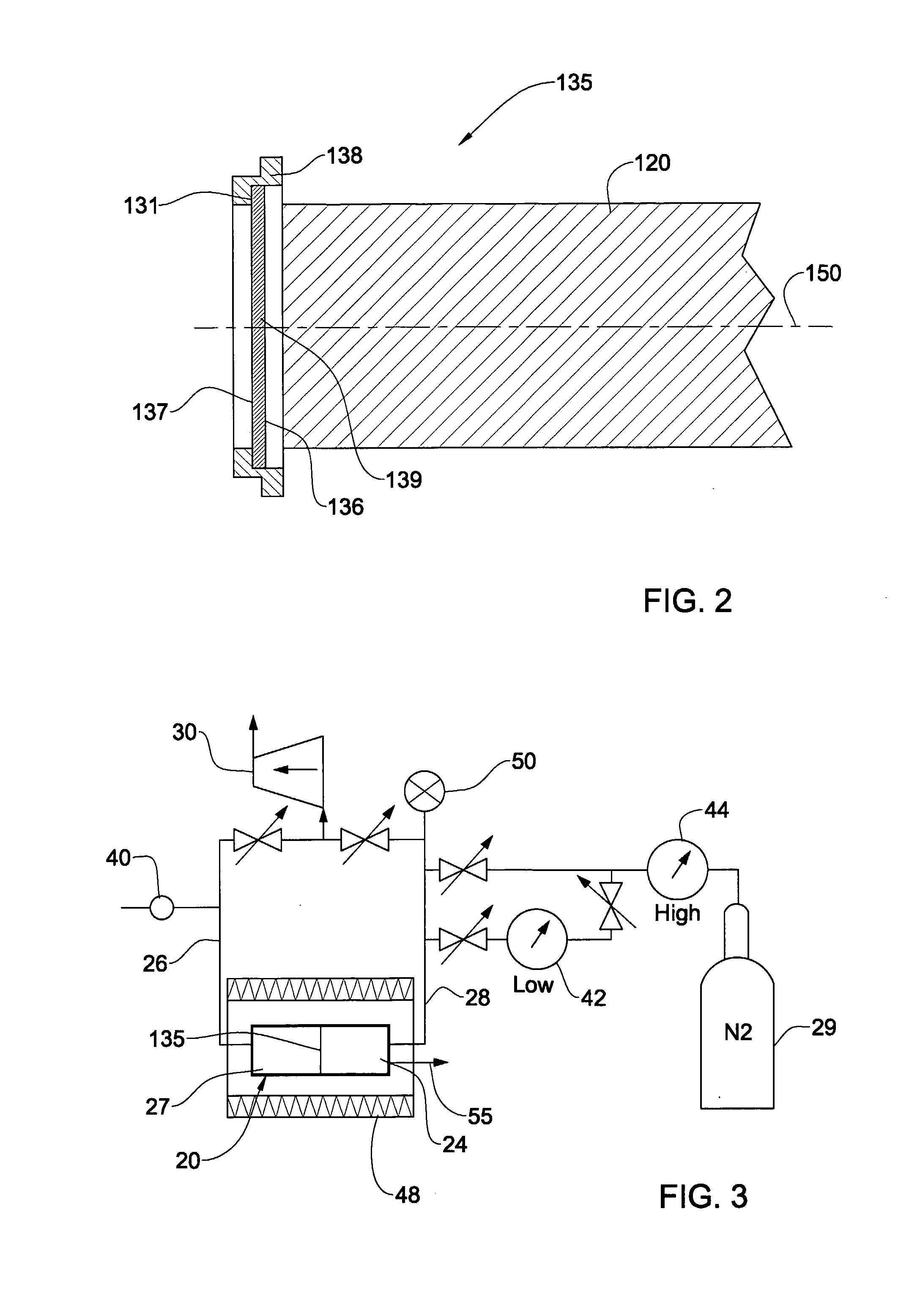
[0026] The target is held in a target station and positioned such that the beam can directly interact with it (in the case of protons, alpha particle or deuterons), or indirectly (in the case of neutrons) on one face of the target. The target is typically in the form of a foil of target material held in a mechanically stable frame that is configured to be mounted onto the target station. Targets are typically disc-like and circular, but may be any other shape such as polygonal, oval etc., and, in some embodiments, are aligned orthogonally to the incident particle beam. In other embodiments, the targets are aligned at an angle to the beam, thereby reducing the effective beam density impinging on the target. In some embodiments the target material may be plated or otherwise deposited onto a substrate made from a different material. In yet other embodiments, heat-sink materials, such as indium, or graphite, are provided as an intermediate layer between the target material layer and the substrate layer. The intermediate layer may be configured to melt when the system is in operation, and the melted layer provides improved thermal contact between the target layer and the substrate layer.
[0028] In some embodiments, the target station may be configured for easy removal of the target, which may be fitted to a cartridge-like frame, and in a manner that prevents contamination or communication between the vacuum of the linear accelerator, and the cooling fluid of the cooling means.

Problems solved by technology

Many such radioisotopes, using conventional transmutation techniques based on prior art particle accelerators are often not possible to produce at all, are produced with a relatively low yield, or are expensive to produce, requiring long irradiation times. For example, Table I below shows a number of exemplary isotopes, some of which cannot be produced by prior art particle beam methods, and the others of which are produced in relatively low yields per unit time on account of the relatively low power density used.
The costs associated with the former are often very high, and for many isotopes, uneconomic.
Such a process is time consuming and cumbersome and produces a relatively low yield of radioisotopes.
Moreover, the copper backing tends to affect the isotope production by partially transmuting to zinc, which also needs to be removed from the final product.
It is believed that the use of high power continuous wave particle beams (in the order of 100 MeV) may have disadvantages, such as the production of unwanted isotopes and radioactivation side effects usually associated with them.
This publication concluded that increasing the incident deuteron energy above 20 MeV was not a profitable exercise for the production of 103Pd.)
In any case, while such problems are much less significant in lower power particle beams, the limited current available in conventional accelerators seriously limits the ability of such accelerators to produce isotopes economically.
However, the beam energy is limited to 20 MeV, which does not allow the production of several important isotopes, such as for example 201Tl.
Further, it is well known that pulsed power surges generated by such systems cause thermal stresses in targets which lead to irreversible damage of the same.
Any attempt at using increased current or power of a continuous wave particle beam is not a straightforward undertaking, and would necessitate additional cooling preparations, which is also not a straightforward proposition.
Further, the cooling capacity must also be such as to maintain the target at a temperature below that at which it begins to lose mechanical integrity, otherwise the target can break down and the cooling material (especially if a fluidic material is used) can contaminate the particle beam accelerator itself.
The reference further infers that at nozzle to target distances less than unity there would be a significant increase in flow resistance resulting in the need for extremely large system pressures.

Method used


Image

  • Method And System For Production Of Radioisotopes, And Radioisotopes Produced Thereby
  • Method And System For Production Of Radioisotopes, And Radioisotopes Produced Thereby
  • Method And System For Production Of Radioisotopes, And Radioisotopes Produced Thereby

Examples


example 1

Production of Carrier-Free Lutetium 177 (177Lu)

[0118] a. Irradiation Step

[0119] A natural ytterbium (176Yb) foil (provided from Goodfellow Inc, UK, 99.99% pure), dimensions of the foil are: 100×13 mm, and 100-250 micron thick, and is irradiated by a deuteron beam at a continuous wave (cw) current of up to 2 mA according to the invention. The irradiation energy is 15-20 MeV (power=30 to 40 kW, power density 2.3 to 3.0 kW / cm2)

[0120] The irradiation time is 10 hours. The foil is cooled at its back side by eutectic mixture of Indium-Gallium (about 24.5 / 75.5 ratio respectively). Following the irradiation the target-foil is disconnected from the cooling system and transferred to a chemistry processing hot cell.

[0121] b. Purification Process

[0122] Target Dissolution

[0123] The irradiated ytterbium target is transferred to a hot cell according to the invention and immersed 1N HCl for 1 hour until complete dissolution of the foil occurs.

[0124] Chemical Separation of Lutetium From Ytter...

example 2

Production of Palladium 103 (Pd-103)

[0132] a. Irradiation Step

[0133] A natural rhodium (103Rh) foil (provided from Johnson Matthey Noble Metals Inc., 99.99% pure) is used as a target for irradiation. The foil is oval with dimensions of 100×12 mm, and 150-250 μm thick. The foil is irradiated by a deuteron beam in a continuous wave (cw) current of up to 2 mA according to the present invention. The irradiation energy is 17 MeV and irradiation time is 12-36 hours (power=34 kW, power density 2.8 kW / cm2)

[0134] The foil is cooled on its back side by eutectic mixture of indium-gallium (about 24.5 / 75.5 ratio respectively)

[0135] Following the irradiation the target is disconnected from the cooling system, and transferred for chemical processing in a hot cell.

[0136] b. Purification Process

[0137] The purification step (chemical) includes two major steps: (I) target dissolution, and (II) chemical separation between palladium and rhodium,

[0138] Target Dissolution

[0139] The target is disso...


PUM


Abstract

A system and method for the production of radioisotopes by the transmutation of target isotopic material bombarded by a continuous wave particle beam. An ion source generates a continuous wave ion beam, irradiating an isotope target, which is cooled by transferring heat away from the target at heat fluxes of at least about 1 kW / cm2.

Description

FIELD OF THE INVENTION [0001] This invention relates to the production of radioisotopes, in particular by transmutation techniques. The invention is also concerned with cooling systems suitable for use in the production of such radioisotopes. BACKGROUND OF THE INVENTION [0002] Transmutation of a target material to produce radioisotopes is a well-known process in which atomic nuclei in the target material interact with bombarding particles, forming compound nuclei which then decay into the desired product isotope, via the emission of one or more of elementary particles, atomic nuclei, and gamma rays. The transmutation process is typically followed by a separation process, which may be chemical or isotopic for example, to provide the pure radioisotope product. The production of radioisotopes is a critical element in a plurality of medical procedures, including diagnostic and therapeutical procedures, for example: thallium-201 (201Tl) for cardiology applications; indium-111 (111In), lu...

Claims


Application Information

Patent Timeline
IPC IPC(8): G21G1/10G21C7/32G21G1/00
CPCH05H6/00G21G1/10
Inventor LAVIE, EFRAIMSILVERMAN, IDOARENSHTAM, ALEXANDERKIJEL, DANIELBROSHI, LEASAYAG, ELIAHU
Owner SOREQ NUCLEAR RES CENT ISRAEL ATOMIC ENERGY COMMISSION
Learn More