Method for producing and depositing nanoparticles

a nanoparticle and nanoparticle technology, applied in the direction of vacuum evaporation coating, nickel oxide/hydroxide, transportation and packaging, etc., can solve the problems of nanoparticle aggregation, organic solvents and additives, and the introduction of impurities, so as to increase the laser fluence, high laser fluence, and the effect of increasing the laser fluen

Inactive Publication Date: 2008-01-10
IMRA AMERICA
View PDF29 Cites 50 Cited by
  • Summary
  • Abstract
  • Description
  • Claims
  • Application Information

AI Technical Summary

Benefits of technology

[0013]As discussed above, one consequence of plasma formation is that the mass fraction of nanoparticles in the total mass of the material removed from the target or the total mass deposited on the substrate decreases with the increasing laser fluence. Particularly, by using a laser fluence between Fth1 and Fth2 the ablated material is mostly composed of nanoparticles, and for applications where the presence of some mesoparticles and atomic species does not significantly affect performance, the fluence range for particle generation can be extended up to 3Fth2. On the other hand, by using a laser fluence above 3Fth2, the ablated material is mostly in the form of gas with negligible amounts of particles. Therefore, nanocomposite thin-films, which are composed of nanoparticles embedded in thin films, and superlattice structures with alternatively deposited nanoparticles and thin-films, can be fabricated by modulating the laser fluence between two regimes, i.e., below and above 3Fth2. In addition, a variety of material combinations can also be easily realized by shifting between target materials inside the chamber.
[0014]That the appearance of a stabilized mesoparticle population is coincident with the threshold Fth2

Problems solved by technology

However, the synthesis of nanoparticles in a controlled manner, in terms of impurities, stoichiometry, crystallinity, homogeneity, and size uniformity, is still a challenge for practical applications.
Chemical methods often result in aggregations of nanoparticles, and impurities introduced by the organic solvents and additives is also a problem.
Physical methods usually do not have satisfactory control over the particle size and homogeneity.
However, in spite of the advantages of pulsed laser ablation in the production of nanoparticles, processes developed with a clear understanding of the critical parameters that determine the particle characteristics are not yet av

Method used


Image

  • Method for producing and depositing nanoparticles
  • Method for producing and depositing nanoparticles
  • Method for producing and depositing nanoparticles

Examples


Embodiment Construction

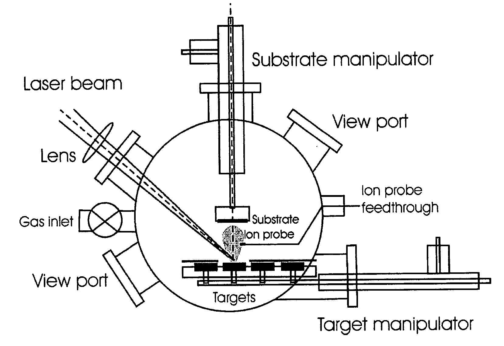
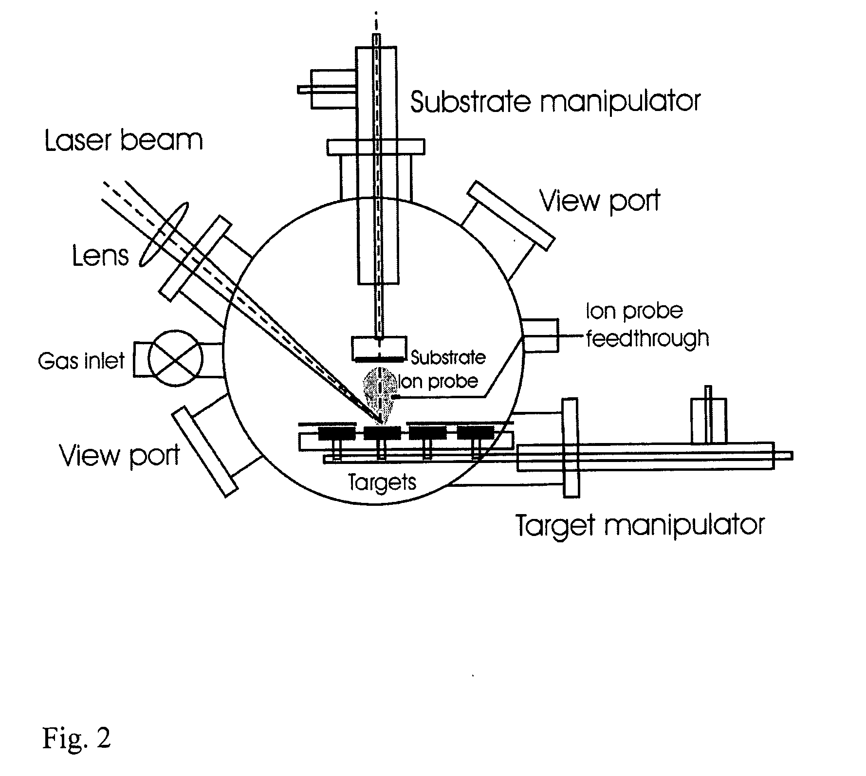
[0023]FIG. 2 illustrates the system used in this invention. The system includes a vacuum chamber 1 pumped by a turbo pump and a mechanical pump (not shown), a target manipulator 2 which provides for rotational and lateral movement for four targets of different materials, a substrate manipulator 3 which provides heating and rotational and lateral movements for the substrate 10, a gas inlet 4, and an ion probe 6 (Langmuir probe) to measure the ion current of the ablation plume. When measuring the ion current, the ion probe is biased −50 V relative to the ground to collect the positive ions in the plume (the number of negative ions in plasma is negligible). An ultrafast laser (not shown in the figure) is positioned outside the chamber and the laser beam 20 is focused onto the target surface through a fused silica window 21. The laser has a pulse duration between 10 fs-50 ps, preferably between 10 fs-1 ps; a pulse energy between 100 nJ-10 mJ; and a repetition rate greater than 1 kHz. Th...


PUM

PropertyMeasurementUnit
Fractionaaaaaaaaaa
Fractionaaaaaaaaaa
Sizeaaaaaaaaaa

Abstract

The present invention provides a one-step process for producing and depositing size-selected nanoparticles onto a substrate surface using ultrafast pulsed laser ablation of solid target materials. The system includes a pulsed laser with a pulse duration ranging from a few femtoseconds to a few tens of picoseconds, an optical setup for processing the laser beam such that the beam is focused onto the target surface with an appropriate average energy density and an appropriate energy density distribution, and a vacuum chamber in which the target and the substrate are installed and the background gases and their pressures are appropriately adjusted.

Description

FIELD OF THE INVENTION[0001]This invention is related to a process of producing and depositing size-selected metal and metal oxide nanoparticles onto a substrate surface using ultrafast pulsed laser ablation.DESCRIPTION OF THE PRIOR ART AND BACKGROUND OF THE INVENTION[0002]Nanoparticles of various materials such as metal, metal oxide, and semiconductors have recently attracted much attention from academia and industry because of their unique chemical and physical properties which dramatically differ from those of their bulk counterparts. Promising applications of nanoparticles have been explored in many areas, including magnetics, photonics, catalysts, sensors, and biomedicines. However, the synthesis of nanoparticles in a controlled manner, in terms of impurities, stoichiometry, crystallinity, homogeneity, and size uniformity, is still a challenge for practical applications.[0003]In general, methods of producing nanoparticles can be put into two categories: chemical method (wet pro...

Claims


Application Information

Patent Timeline
IPC IPC(8): C23C14/00
CPCB22F9/12B22F2998/00B22F2999/00C01G53/04C01P2004/04C01P2004/51C23C14/28B22F1/0018B22F2202/11B22F1/054
Inventor LIU, BINGHU, ZHENDONGCHE, YONG
Owner IMRA AMERICA
Why Eureka
Try Eureka