High power discharge fuel ignitor

a fuel ignitor and high-power discharge technology, which is applied in the manufacture of sparking plugs, machines/engines, sparking plugs, etc., can solve the problems of high coulomb transfer of high-power discharge, inefficient design, and complex engine operation, and achieve the effect of effectively reducing electrode erosion and fine cross sectional electrodes

Active Publication Date: 2008-01-24
PASSAIC RIVER CO INC
View PDF41 Cites 31 Cited by
  • Summary
  • Abstract
  • Description
  • Claims
  • Application Information

AI Technical Summary

Benefits of technology

[0029] The present invention advantageously provides an ignition device having a very fine cross sectional electrode of a material and design to effectively reduce the electrode erosion prevalent in high power discharge, spark-gap devices, and an insulator constructed in such a manner as to create a capacitor in parallel with the high voltage circuit of the ignition system, and a method by which to apply a conductive coating to the inside and outside diameter of the ignitor insulator forming the oppositely charged plates of an integral capacitor. The present invention also provides for the placement of an inductor or resistor within the ignitor whereby the resistor or inductor suitably shields any electromagnetic or radio frequency emissions from the ignitor without compromising the high power discharge of the spark, and a method of completing the capacitor and high voltage circuit of the ignition system to provide a path for the high power discharge to the electrode of the ignitor.

Problems solved by technology

While these materials will reduce electrode erosion for typical low power discharge (less than 1 ampere peak discharge current) spark plugs and perform to requirements for 109 cycles, they will not withstand the high coulomb transfer of high power discharge (greater than 1 ampere peak discharge current).
While this will increase the discharge power of the spark, the designs are inefficient, complex and none deal with the accelerated erosion associated with high power discharge.
The use of two spark gaps in a singular spark plug to ignite fuel in any internal combustion spark ignited engine that utilizes electronic processing to control fuel delivery and spark timing could prove fatal to the operation of the engine as the EMI / RFI emitted by the two spark gaps could cause the central processing unit to malfunction.
Capacitance is not disclosed and nowhere is there any mention of the electromagnetic and radio frequency interference created by the non-resistor spark plug, which if not properly shielded against EMI / RFI emissions, could cause the central processing unit to shut down or even cause permanent damage.
Any degradation of the paths by migration of the ceramic material inherent in the cermet ink reduces the efficacy and operation of the electrical device.
These applications are likely not sufficient to resist the electrode wear associated with high power discharge.
The ignition transformer or coil is limited in the amount of voltage delivered to the spark plug.
The increase in spark gap due to accelerated erosion and wear could be more than the voltage available from the transformer, which could result in misfire and catalytic converter damage.
U.S. Pat. No. 6,771,009 discloses a method of preventing flashover of the spark and does not resolve issues related to electrode wear or increasing spark discharge power.
The combination is said to reduce electrode erosion but does not claim to either reduce erosion in a high-power discharge condition or improve spark power.
U.S. Pat. No. 6,819,030 for a spark plug claims to reduce ground electrode temperatures but does not claim to reduce electrode erosion or improve spark power.

Method used


Image

  • High power discharge fuel ignitor
  • High power discharge fuel ignitor
  • High power discharge fuel ignitor

Examples


Embodiment Construction

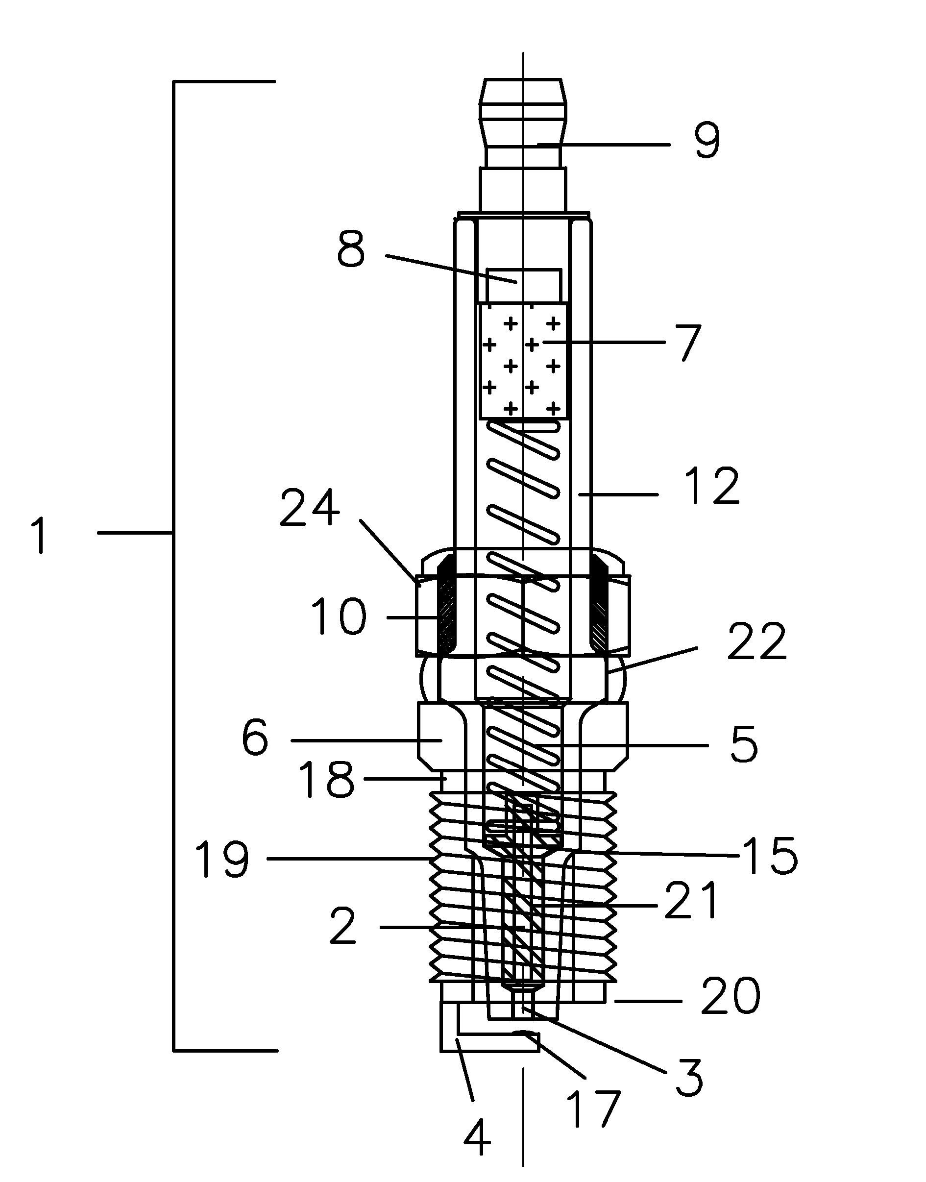
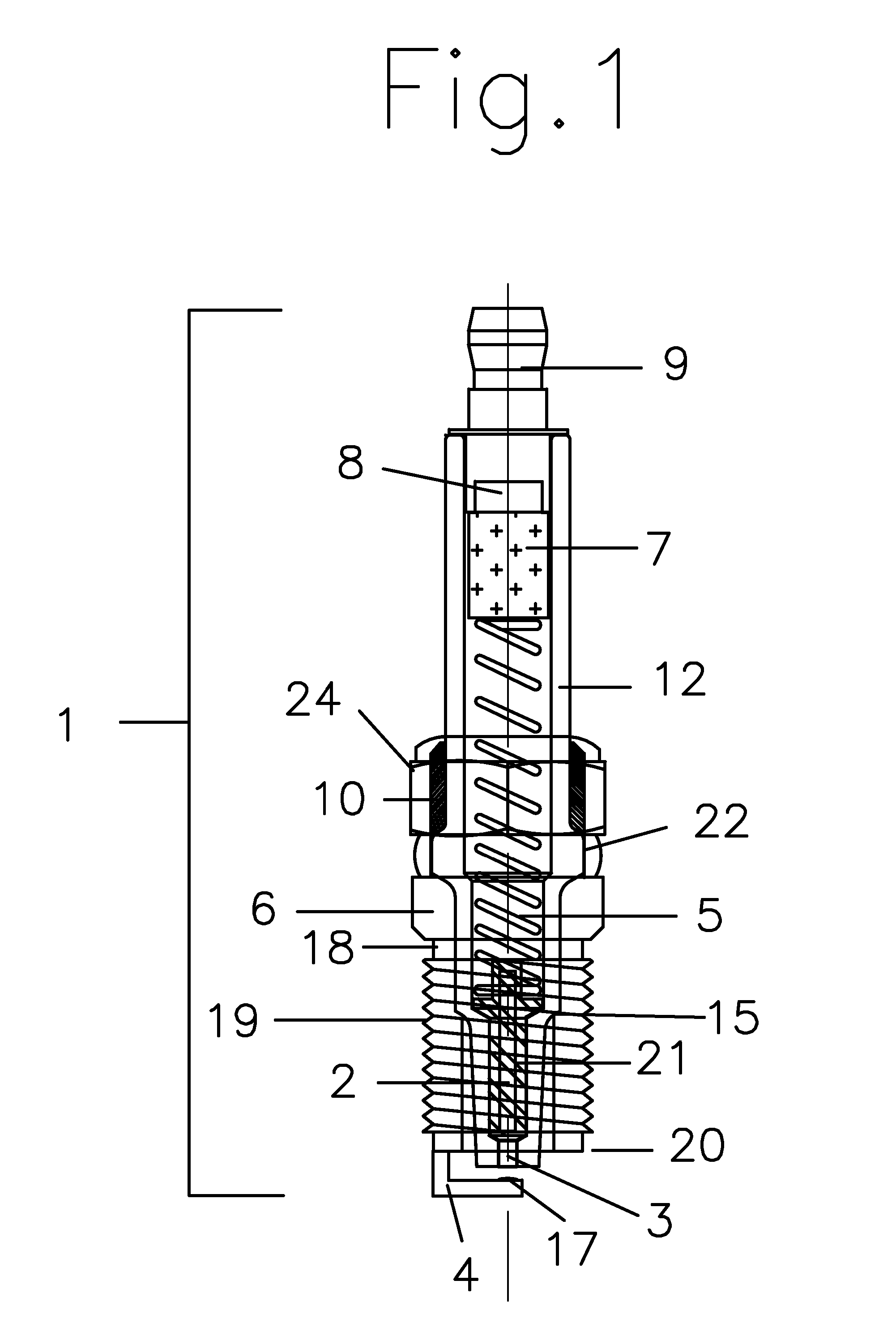
[0042] Referring now to the drawings, in particular FIG. 1, a spark ignited, internal combustion engine ignition device, spark plug, or ignitor in accordance with the present invention is shown generally as 1. The ignitor 1 consists of a metal casing or shell 6 having a cylindrical base 18, which may have external threads 19, formed thereon for threading into the cylinder head (not shown) of the spark ignited internal combustion engine. The cylindrical base 18, of the ignitor shell 6 has a generally flattened surface perpendicular to the axis of the ignitor 1 to which a ground electrode 4 is affixed by conventional welding or the like. In an embodiment of the invention, the ground electrode 4 has a rounded tip 17 extending therefrom and preferably formed from a rhenium / molybdenum sintered compound, which resists the erosion of the electrode due to high power discharge, as further disclosed herein.

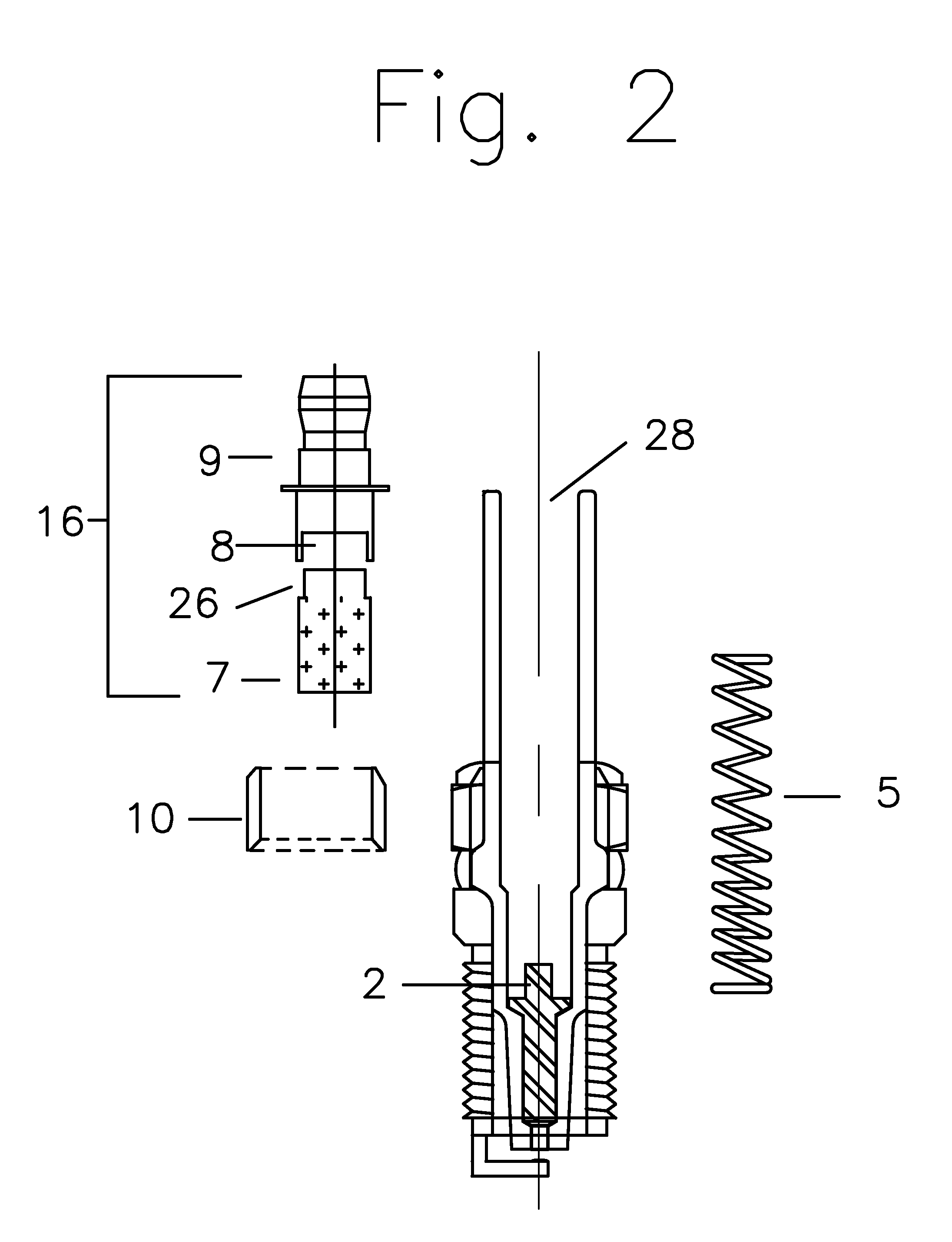
[0043] Ignitor 1 further includes a hollow ceramic insulator 12 disposed concentricall...


PUM


Abstract

A spark-ignited, internal combustion engine ignition device to increase electrical transfer efficiency of the ignition by peaking the electrical power of the spark during the streamer phase of spark creation and improving combustion quality, incorporating an electrode design and materials to reduce electrode erosion due to high power discharge, an insulator provided with capacitive plates to peak the electrical current of the spark discharge, and concomitant methods.

Description

CROSS-REFERENCE TO RELATED APPLICATIONS [0001] This application claims priority to and the benefit of the filing of U.S. Provisional Patent Application Ser. No. 60 / 820,031, entitled “High Power Discharge Fuel Ignitor”, filed on Jul. 21, 2006, and the specification thereof is incorporated herein by reference.BACKGROUND OF THE INVENTION [0002] The present invention relates to spark plugs used to ignite fuel in internal combustion spark-ignited engines. Present day spark plug technology dates back to the early 1950's with no dramatic changes in design except for materials and configuration of the spark gap electrodes. These relatively new electrode materials such as platinum and iridium have been incorporated into the design to mitigate the operational erosion common to all spark plugs electrodes in an attempt to extend the useful life. While these materials will reduce electrode erosion for typical low power discharge (less than 1 ampere peak discharge current) spark plugs and perform...

Claims


Application Information

Patent Timeline
Patent Type & Authority Applications(United States)
IPC IPC(8): H01T21/00H01T13/39H01T21/02
CPCF02P3/08H01T21/02H01T13/41H01T13/40F02P3/06F02P13/00H01T13/00
Inventor CAMILLI, LOUIS S.
Owner PASSAIC RIVER CO INC
Why Eureka
Try Eureka