
Combustible gas detector, process for producing combustible gas detector, and fuel cell system equipped with combustible gas detector

Inactive Publication Date: 2008-02-14
CANON KK
View PDF9 Cites 28 Cited by
  • Summary
  • Abstract
  • Description
  • Claims
  • Application Information

AI Technical Summary

Benefits of technology

[0038]In view of the above problems to be solved, an object of the present invention is to provide a combustible gas detector with a low power consumption, a low noise and a high speed response which enable miniaturization; a process for producing the combustible gas detector; and a fuel cell system equipped with a combustible gas detector.

Problems solved by technology

Liquefying hydrogen needs a large energy and also involves a problem that liquid hydrogen may spontaneously vaporize and leak, but the method enables high-density storage.
This method has a problems that, due to large specific gravity of the hydrogen storing alloys, hydrogen of merely 2 wt % or so can be occluded in weight base and that the fuel tank is heavy, but since the occluded amount is large in volume base, the method is effective for miniaturization.
However, there is a problem in this method that impurity gases such as nitrogen and steam penetrates the electrolyte film and are accumulated in the fuel channel, which causes decrease in the power generation characteristics with time.
However, the conventional gas sensors for detecting combustible gas described above have the following problems.
For example, the adsorption type gas sensors have very poor stability and response at the normal temperature, and a method of warming the device with a heater is used to improve the response.
However, when a heater is used, electricity should be continuously applied to the exothermic body even during standby time, which causes a problem that the power consumption of the sensor increases.
The gas heat conduction-type combustible gas sensors are not suitable for sensors detecting combustible gas of a concentration around several % because the detectable combustible gas concentration (hereinbelow, referred to as detection limit concentration) by such sensors is high.
In addition, electricity should be continuously applied to the exothermic body even during standby time, which causes a problem that the power consumption of the sensor increases.
Besides, conventional combustible gas sensors of adsorption type, catalytic combustion type, gas heat conduction type and the like detected the change in the voltage or electrical resistance as an analog signal and consequently they were susceptible to noise.
Furthermore, miniaturization of processing circuit of the detection signal was difficult, and many of them always used electricity.
In addition, the conventional combustible gas detectors as described above had problems that miniaturization thereof was not sufficient and that power consumption thereof was not small, and therefore required a system having a larger size and an excessive energy in the case of using fuel cells for small size electric apparatuses.

Method used


Image

  • Combustible gas detector, process for producing combustible gas detector, and fuel cell system equipped with combustible gas detector
  • Combustible gas detector, process for producing combustible gas detector, and fuel cell system equipped with combustible gas detector
  • Combustible gas detector, process for producing combustible gas detector, and fuel cell system equipped with combustible gas detector

Examples


first embodiment

[0085]In the first embodiment, the constitution example of the combustible gas detector using a cantilever for a flexible member is described.

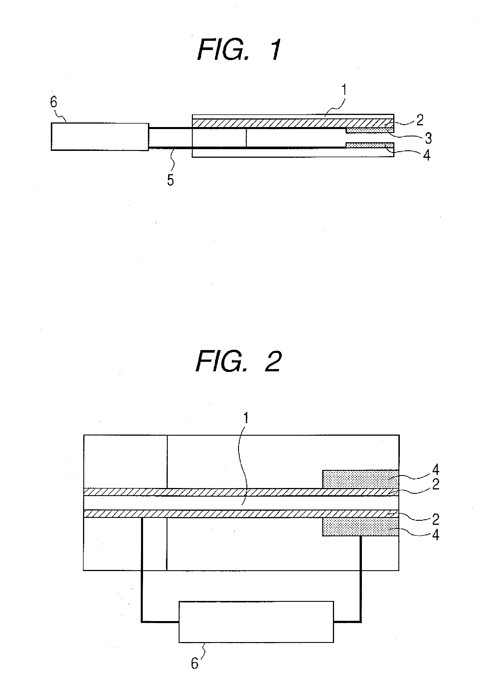
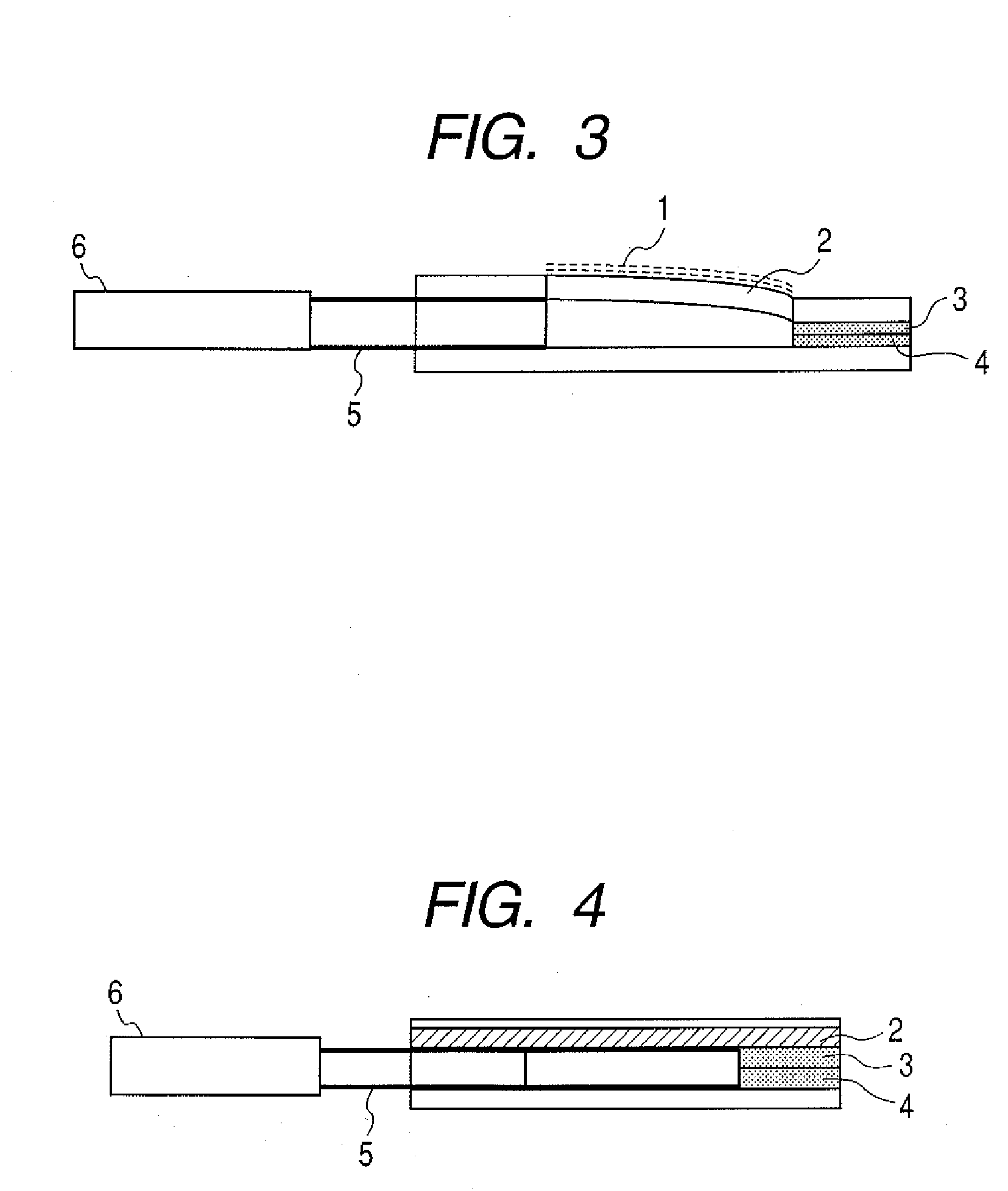
[0086]FIG. 1 shows a side cross sectional view illustrating the combustible gas detector in this embodiment. FIG. 2 shows the top view thereof.

[0087]The combustible gas detector according to this embodiment includes a catalytic layer 1, a cantilever 2 having a displacement layer, an upper electrode 3, a lower electrode 4, a wiring 5 and a detector 6.

[0088]Here, when hydrogen is selected as a detection gas, for example, platinum is suitable as a material constituting the catalytic layer 1. When carbon monoxide is contained in the detection atmosphere, catalyst poisoning by carbon monoxide can be prevented by using a compound of platinum and ruthenium.

[0089]In the example illustrated by FIG. 1, the cantilever 2 consists only of a displacement layer. The cantilever does not necessarily consist only of a displacement layer and may have a flexible ...

second embodiment

[0117]As the second embodiment, the constitution example of the combustible gas detector using a diaphragm for a flexible member is described.

[0118]FIG. 11 shows a side cross sectional view illustrating the combustible gas detector in this embodiment. FIG. 12 shows the top view thereof.

[0119]The combustible gas detector according to this embodiment includes a catalytic layer 101, a displacement layer (diaphragm) 102, an upper electrode 103 constituting a pair of electrode pads, a lower electrode 104, a wiring 105 and a detector 106.

[0120]Here, when hydrogen is selected as a detection gas, for example, platinum is suitable as a material constituting the catalytic layer 101. When carbon monoxide is contained in the detection atmosphere, catalyst poisoning by carbon monoxide can be prevented by using a compound of platinum and ruthenium.

[0121]When a detection gas contacts with the catalytic layer 101, catalyzed combustion occurs by reacting with oxygen in the atmosphere and heat is gen...

example 1

[0139]In Example 1, a constitution example of the combustible gas detector which uses a bimetal cantilever as a flexible member.

[0140]The combustible gas detector of this Example can be produced by conventional machining technique, but, here, the production process using semiconductor processing technique is described. Size and materials of each part may be variously combined. One example of those is shown here.

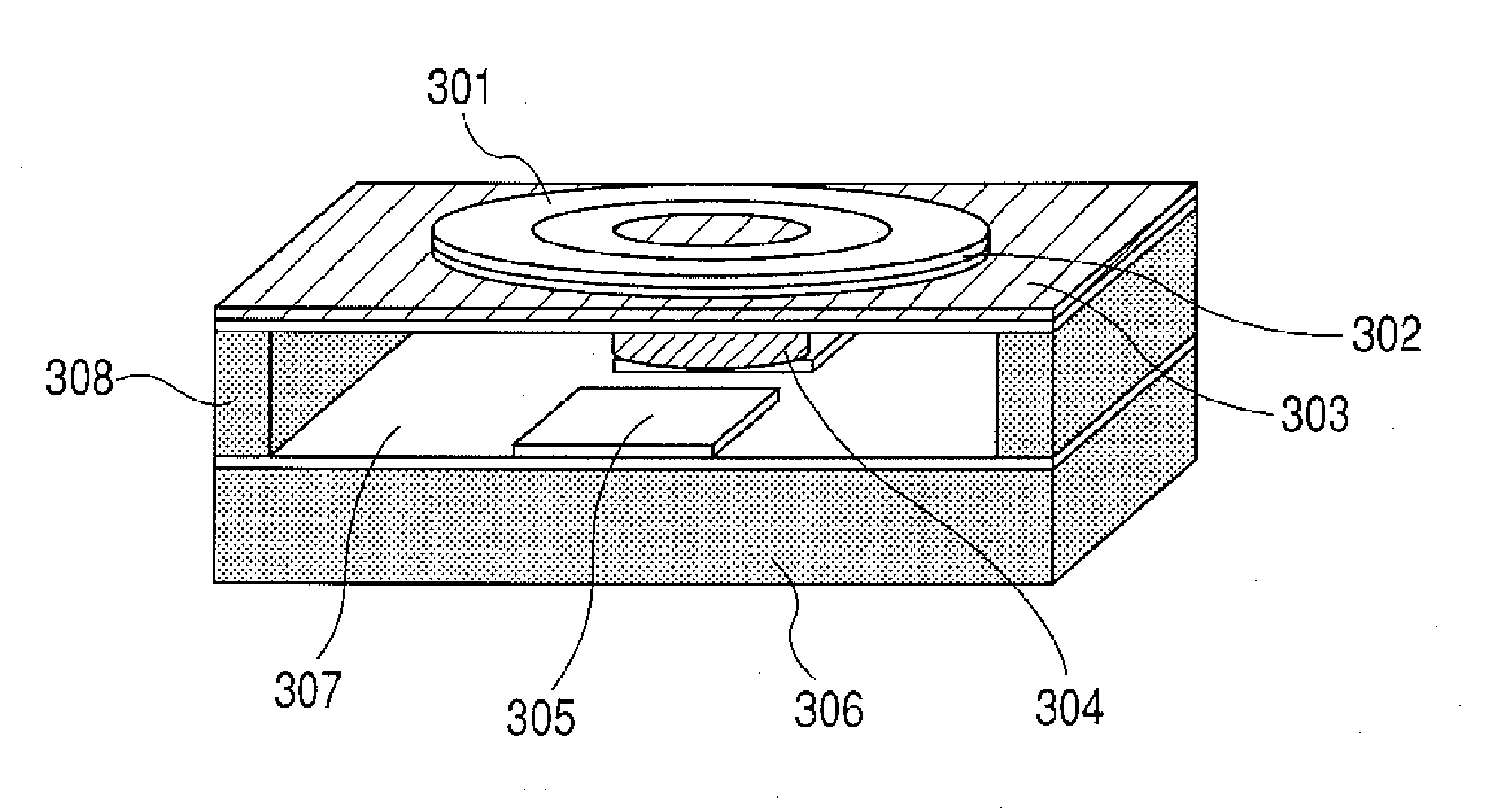
[0141]A perspective view illustrating the constitution example of the combustible gas detector of this Example is shown in FIG. 13.

[0142]The combustible gas detector of this Example has an oxide layer 207 for electrical insulation and heat insulation and a lower electrode 205 on a silicon substrate 206.

[0143]A cantilever is provided on a supporting layer 208 made of nickel.

[0144]The cantilever has an aluminum layer and a platinum layer on a silicon beam, and a bimetal lower layer 203 made of silicon and a bimetal upper layer 202 made of aluminum form a bimetal, and platinum f...


PUM


Abstract

A combustible gas detector which has low power consumption, low noise and high speed response and which enable miniaturization, a process for producing the combustible gas detector, and a fuel cell system equipped with a combustible gas detector are provided. The combustible gas detector for detecting a combustible gas includes a catalyst for reaction with the combustible gas, a first displacement unit including a flexible member which is displaced with catalytic combustion by the reaction of the catalyst with the combustible gas, and electrical contacts which are switched by the displacement of the flexible member in the first displacement unit.

Description

BACKGROUND OF THE INVENTION[0001]1. Field of the Invention[0002]The present invention relates to a combustible gas detector for detecting a combustible gas, a process for producing the combustible gas detector, and a fuel cell system equipped with the combustible gas detector.[0003]2. Description of the Related Art[0004]As the development of hydrogen utilization technology such as fuel cells advances, the importance of combustible gas sensors increases so as to more safely control these systems.[0005]For example, it is known that hydrogen explodes if it is present at a concentration of 4 to 75% in the air. In case that a combustible gas leaks to the outside by system failure or when purging (scavenging) operation is necessary for driving the system, it is necessary to keep ignition source away from the explosible concentration area. Recently, not only the development of in-car types and at-home stationary types but also the development of small size fuel cells for mobile devices as ...

Claims


Application Information

Patent Timeline
IPC IPC(8): G01N31/12B05D5/12H01M8/00
CPCH01M8/04246G01N27/16Y02E60/50Y02P70/50
Inventor NAKAKUBO, TORU
Owner CANON KK
Learn More