Source Of Generating Multicharged Ions And Charged Particle Beam Apparatus Using Such Ion Generating Source

a technology of charged particle beam and source, which is applied in the direction of ion beam tubes, magnetic discharge control, instruments, etc., can solve the problems of large amount of time required in assembling and aligning, the apparatus is expensive and costly in operation to obtain high beam intensity, and the degree of vacuum cannot be obtained. , to achieve the effect of light weight and small siz

Inactive Publication Date: 2008-04-17
JAPAN SCI & TECH CORP
View PDF2 Cites 10 Cited by
  • Summary
  • Abstract
  • Description
  • Claims
  • Application Information

AI Technical Summary

Benefits of technology

[0029]According to the structure mentioned above, the specimen is irradiated with desired multicharged ions selected at the ion separator from various multicharged ions generated by the multicharged ions generating source. The means for treating the surface of the specimen allows cleaning a specimen surface prior to irradiation with multicharged ions. Also, the inspecting me

Problems solved by technology

There have been the problems, however, that the apparatus is expensive and costly in operation to obtain high beam intensity.
In separating the superconducting magnet from the ion source electrode, however, this apparatus entails breaking vacuum in the ion source electrode.
As a result, the EBIS of Prior Art 6 due to weak heat resistance in a region of its superconducting magnet cannot have enough degree of vacuum obtained unless it is pumped continuously over an extremely long period of time.
Further, while in the EBIS the electron source, drift tube and collector must have their central axes mutually aligned with due precision, considerable amounts of time are required in their assembling and alignment since with the superconducting magnet unassembled it is not possible for the ion source electrode alone to be aligned axially.
The multicharged ions generating sources according to Prior Arts 1 to 5 entai

Method used


Image

  • Source Of Generating Multicharged Ions And Charged Particle Beam Apparatus Using Such Ion Generating Source
  • Source Of Generating Multicharged Ions And Charged Particle Beam Apparatus Using Such Ion Generating Source
  • Source Of Generating Multicharged Ions And Charged Particle Beam Apparatus Using Such Ion Generating Source

Examples


example

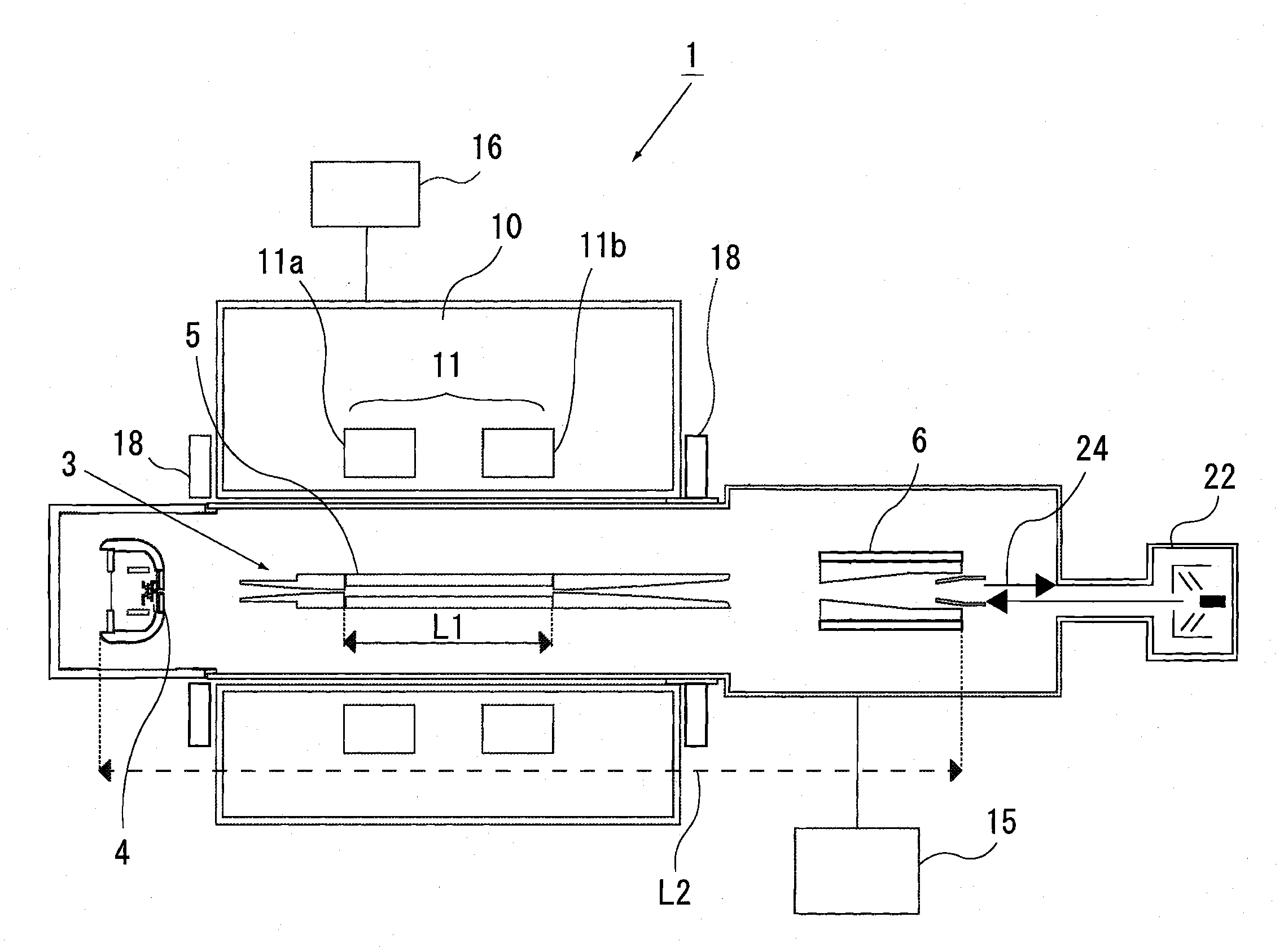
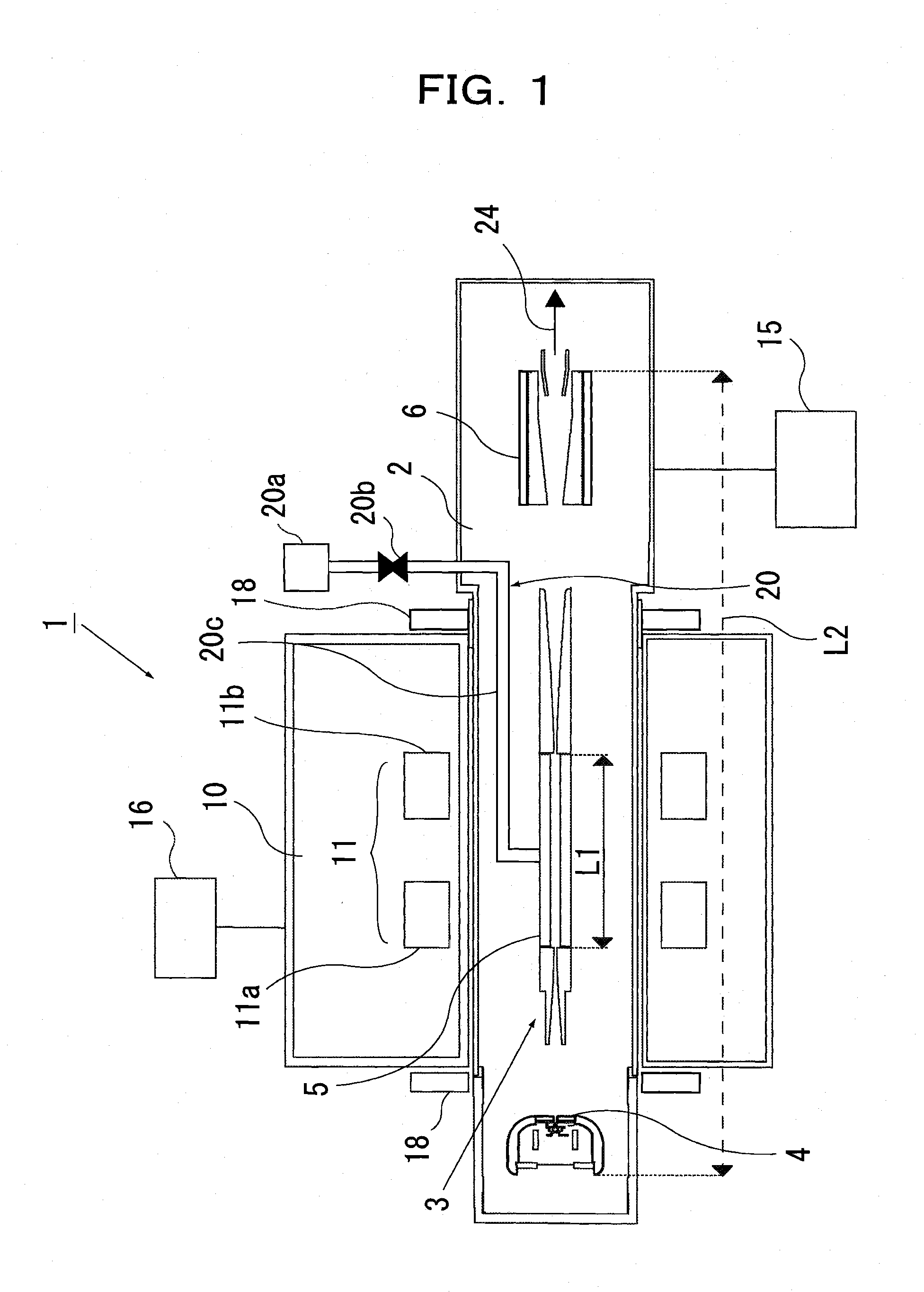
[0070]As a specific example, the multicharged ions generating source 1 was constructed (see FIGS. 1 and 2) that as a superconducting coil a superconducting magnet 11 on the market was disposed in the second vacuum chamber 10 separate from an electron and an ion beam, and it was used an accelerating voltage of 10 to 40 kV, an electron beam current of 300 mA and an ion trapping magnetic field of 3T. A superconducting coil of Helmholtz type was adopted and the drift tube 5 having a length of 200 mm was used to expand the ion trapping region, thereby achieving a higher intensity of the multicharged ions beam 24.

[0071]Mention is next made of a magnetic field by a superconducting magnet and an electron beam trajectory in the multicharged ions generating source 1 of the specific example.

[0072]FIG. 6 is a graph illustrating a magnetic field applied by the superconducting magnet 11 having the Helmholtz coil for use in the multicharged ions generating source 1 in the specific example. In the ...


PUM


Abstract

A multicharged ions generating source that is easy to manufacture, excellent in controllability and maintainability, high in degree of ionization and large in beam intensity and a charged particle beam apparatus using the same are disclosed. The multicharged ions generating source includes an ion source electrode (3) comprising an electron source (4), a drift tube (5) that constitutes an ion trapping region and a collector (6), a superconducting magnet (11) for ion entrapment, an ion infeed means (20, 22), a first vacuum chamber (2) receiving the ion source electrode (3), a second vacuum chamber (10) receiving the superconducting magnet (11), and a vacuum pumping unit (15, 16) provided for each of the first and second vacuum chambers. The first and the second vacuum chambers (2) and (10) are made removable from each other, and only the ion source electrode (3) to be held at extremely high vacuum can be baked for degassing.

Description

TECHNICAL FIELD[0001]The present invention relates to a source of generating multicharged ions and a charged particle beam apparatus using such a multicharged ions generating source.BACKGROUND ART[0002]While removing an electron from an atom forms a positive ion, that which has more than two electrons removed, such as, e.g., Xe44 + ion, is called a positive multicharged ion, which has an extremely large internal energy. It is known that bombarding multicharged ions on a solid surface causes many peculiar phenomena such as emission of a large number of secondary electrons and giving rise to a large structural change in nanometer size around a point of incidence of the multicharged ions (see References 1 and 2 in the list below). Unique interactions of such multicharged ions with a material have focused the spotlight of attention upon their feasible application to processes in a nanometer region such as single-ion implantation and fabrication of a quantum dot (see Reference 3 in the l...

Claims


Application Information

Patent Timeline
IPC IPC(8): H01J27/00
CPCH01J27/205H01J37/04H01J37/08H01J37/3056H01J2237/31735H01J2237/061H01J2237/0815H01J2237/16H01J2237/31701H01J2237/057
Inventor SAKURAI, MAKOTONAKAJIMA, FUMIHARUFUKUMOTO, TAKUNORINAKAMURA, NOBUYUKIOHTANI, SHUNSUKEMASHIKO, SHINRO
Owner JAPAN SCI & TECH CORP
Why Eureka
Try Eureka