Pressurized coal gasifier and coal gasification combined cycle power plant

Inactive Publication Date: 2008-05-22
MITSUBISHI HEAVY IND LTD
View PDF12 Cites 7 Cited by
  • Summary
  • Abstract
  • Description
  • Claims
  • Application Information

AI Technical Summary

Benefits of technology

[0015]According to the pressurized coal gasifier as mentioned in the second means and as claimed in Claim 2, the same function and effect as mentioned with respect to the first means can be obtained. Moreover, even if the load or operational state of the gasifier changes, the water temperature in the water tank can be always appropriately maintained to the set temperature. Hence, an accurate temperature control of the water temperature in the water tank becomes possible and a stably controlled operation of the gasifier can be carried out. This results in a further reduction of the maintenance cost.
[0016]According to the pressurized coal gasifier as mentioned in the third means and as claimed in Claim 3, the same function and effect as mentioned with respect to the second means can be obtained. Moreover, by the circulating water flow control valve being controlled to be opened or closed, quantity of the water supplied into the water tank of the gasifier can be increased or decreased and the water temperature in the water tank can be adjusted and maintained to the set temperature. Thereby, a stably controlled operation of the gasifier can be carried out. Also, in case the circulating water flow control valve is controlled toward a throttling direction, power to drive the circulating pump can be reduced.
[0017]According to the pressurized coal gasifier as mentioned in the fourth means and as claimed in Claim 4, the same function and effect as mentioned with respect to the second means can be obtained. Moreover, by the discharge quantity of the circulating pump being controlled to be increased or decreased, quantity of the water supplied into the water tank of the gasifier can be inc

Problems solved by technology

Thus, at the time of draining from the high pressure gasifier 3 into the atmospheric pressure or at the time of water-feeding from the atmospheric pressure into the gasifier 3, there is a possibility to cause an abrasion damage due to flushing on the downstream side of the control valves or in the pumps and

Method used


Image

  • Pressurized coal gasifier and coal gasification combined cycle power plant
  • Pressurized coal gasifier and coal gasification combined cycle power plant
  • Pressurized coal gasifier and coal gasification combined cycle power plant

Examples


embodiment 1

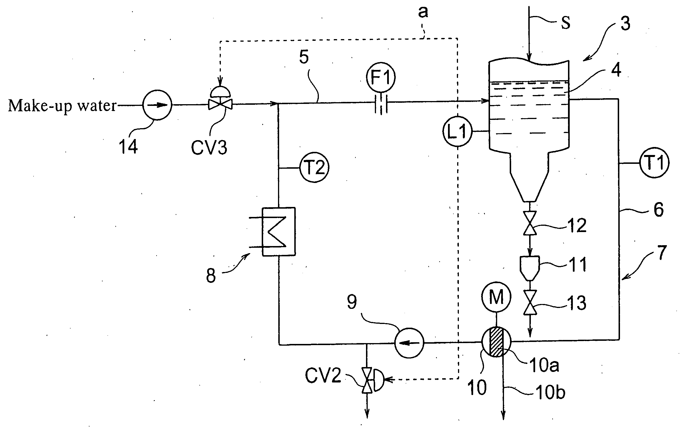
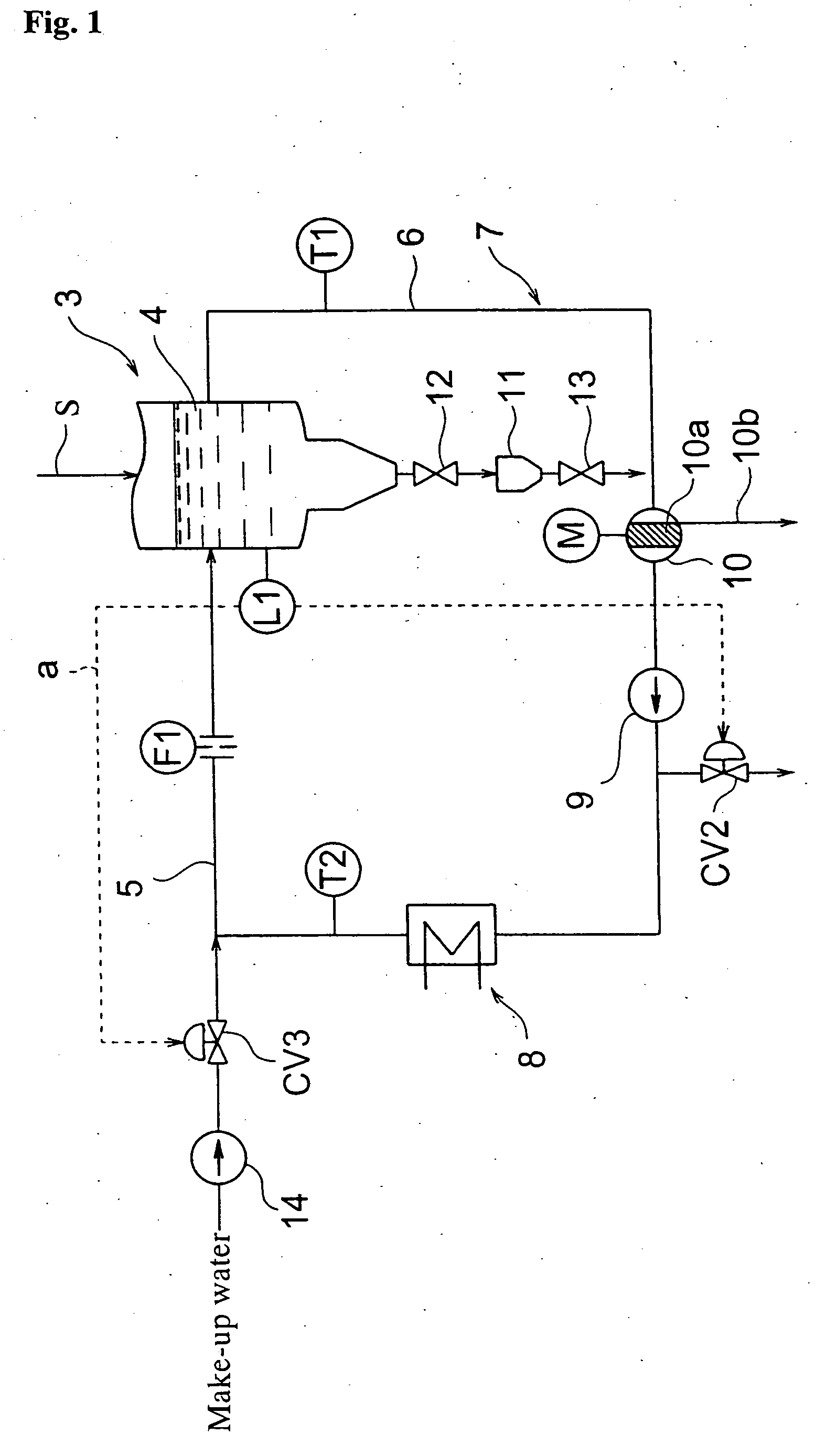
[0032]the pressurized coal gasifier according to the present invention will be described with reference to FIGS. 1 and 5. A pressurized coal gasifier 2 has one portion thereof shown in FIG. 1 and an entire construction thereof shown in FIG. 5. The pressurized coal gasifier 2 is constructed by a coal material supply pipe 3a for supplying a coal material, gasifier 3 for thermally processing the coal material under pressure to be gasified, water tank 4 provided in a bottom portion of the gasifier 3 for water-granulating a slag, gas discharge channel 16 for discharging gas generated in the gasifier 3 and heat exchanger 17 provided in the gas discharge channel 16.

[0033]The coal material fed into the gasifier 3 is a pulverized coal. Also, a coal char collected at a cyclone filter 18 or the like, as shown in FIG. 5, may be fed together into the gasifier 3.

[0034]The water tank 4 is connected with one end of a feed water pipe 5 for supplying water and one end of a drain pipe 6 for draining s...

embodiment 2

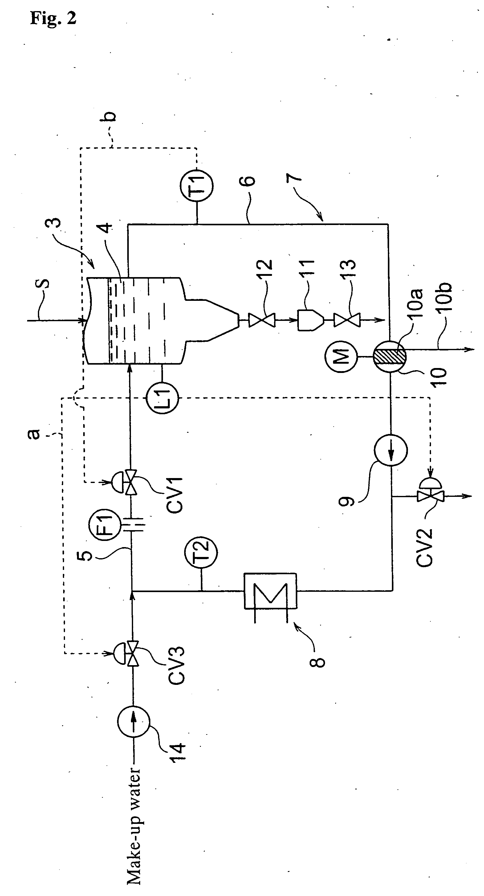
[0043]Next, the pressurized coal gasifier according to the present invention will be described with reference to FIG. 2.

[0044]In the present embodiment, while the device construction of the gasifier 3, water tank 4, circulating channel 7, etc. is the same as that of the embodiment 1, there is additionally provided a temperature adjusting means for controlling opening of a circulating water flow control valve CV1, based on a temperature signal b from the slag hopper water outlet temperature gauge T1. This control by the temperature signal b from the slag hopper water outlet temperature gauge T1 is for controlling the water temperature in the water tank 4 to be lower than the boiling point temperature of the water at the atmospheric pressure, wherein a set temperature of the water at an installation position of the slag hopper water outlet temperature gauge T1 is in the range of 30 to 70° C. If the water temperature exceeds this set temperature, the circulating water flow control valv...

embodiment 3

[0047]the pressurized coal gasifier according to the present invention will be described with reference to FIG. 3.

[0048]In the present embodiment, while the device construction of the gasifier 3, water tank 4, circulating channel 7, etc. is the same as that of the embodiment 1, there is additionally provided a temperature adjusting means for adjusting a drive of the circulating pump 9 by a motor M′ controlled by an inverter 15 to thereby control a pump discharge quantity thereof to be increased or decreased, based on a temperature signal d from the slag hopper water outlet temperature gauge T1. It is to be noted that, in place of the inverter 15, a variable coupling device, such as a fluid coupling, may be used.

[0049]This control by the temperature signal d from the slag hopper water outlet temperature gauge T1 is for controlling the water temperature in the water tank 4 to be lower than the boiling point temperature of the water at the atmospheric pressure, wherein a set temperatur...


PUM


Abstract

Provided is a pressurized coal gasifier in which a general low head pump can be used, abrasion damage of a control valve and pump due to flushing can be prevented and maintenance cost and device cost can be reduced. Also, provided is a coal gasification combined cycle power plant that can efficiently use gas generated by the pressurized coal gasifier for power generation. In a pressurized coal gasifier for thermally processing a coal material under pressure to be gasified, the gasifier having a bottom portion thereof provided with a water tank (4) for water-granulating a slag, the water tank being connected with one end of a feed water pipe (5) and one end of a drain pipe (6), the other ends of the feed water pipe and drain pipe are connected so as to communicate with each other to form a circulating channel (7) of closed system and the circulating channel is provided with a cooler (8) and circulating pump (9) of circulating water.

Description

BACKGROUND OF THE INVENTION[0001]1. Field of the Invention[0002]The present invention relates to a pressurized coal gasifier and a coal gasification combined cycle power plant.[0003]2. Description of the Prior Art[0004]There is known a coal gasifier in which solid carbon material, such as coal, is fed into a gasifier under a pressurized high temperature atmosphere so that combustible components of the material are gasified and heat thereof is recovered as well as a slag as ash component of the material is fed into a quenching water storage of a gasifier bottom portion so that the slag is granulated by water (water-granulated) to be discharged (See Patent Document 1). Also, in the water tank for water-granulating the slag, there is provided a monitoring device for detecting a falling-down state of the slag by image or sound signal, such as a camera for image monitoring or a falling-down sound collector for collecting a falling-down sound of the slag (See Patent Document 2). For cooli...

Claims


Application Information

Patent Timeline
IPC IPC(8): F02B43/00C10J3/68C10J1/207
CPCC10J3/526C10J3/78C10J3/84C10J3/86C10J2300/093Y02E20/16C10J2300/165C10J2300/1671C10J2300/1675C10K1/101Y02E20/18C10J2300/1606Y02P20/129
Inventor TAMURA, KEN
Owner MITSUBISHI HEAVY IND LTD
Why Eureka
Try Eureka