Methods of generating plasma, of etching an organic material film, of generating minus ions, of oxidation and nitriding
- Summary
- Abstract
- Description
- Claims
- Application Information
AI Technical Summary
Benefits of technology
Problems solved by technology
Method used
Image

Examples
experiment 1
[0107]Using such a plasma generator as shown in FIG. 3, glow discharge was caused to occur and a plasma was generated. The stainless steel chamber 1 was roughly discoid shape with a height of 300 mm and a diameter Φ of 300 mm. The chamber 1 had a view window 16, a Langmuir probe 17 and a stainless steel electrode 5, each fixed thereto. The electrode 5 and chamber 1 was insulated from each other with an insulator 14. The height D of the probe was 60 mm, and the diameter E of the electrode 5 was 100 mm. The power source used was a direct-current pulse power source in which an electrostatic induction thyristor device was used.
[0108]The inside of the chamber 1 was evacuated using an oil-sealed rotary pump and a turbo-molecular pump, and argon gas was allowed to flow into the chamber until a pressure of 2.6 Pa. Here, a positive pulse was applied periodically. The crest value of the positive pulse was +10.0 kV, and the frequency was 1 kHz to 10 kHz. The half width of the positive pulse wa...
experiment 2
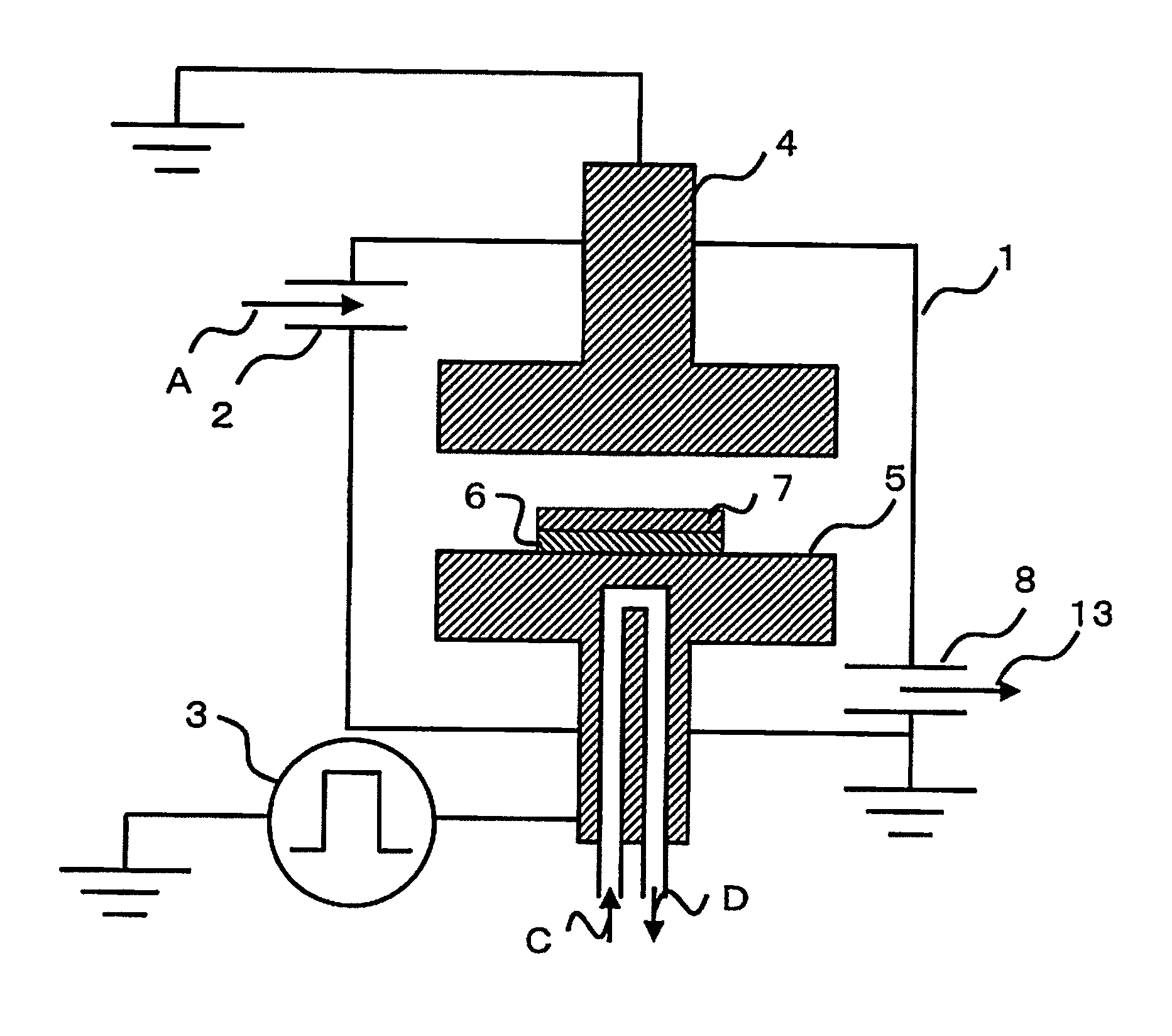
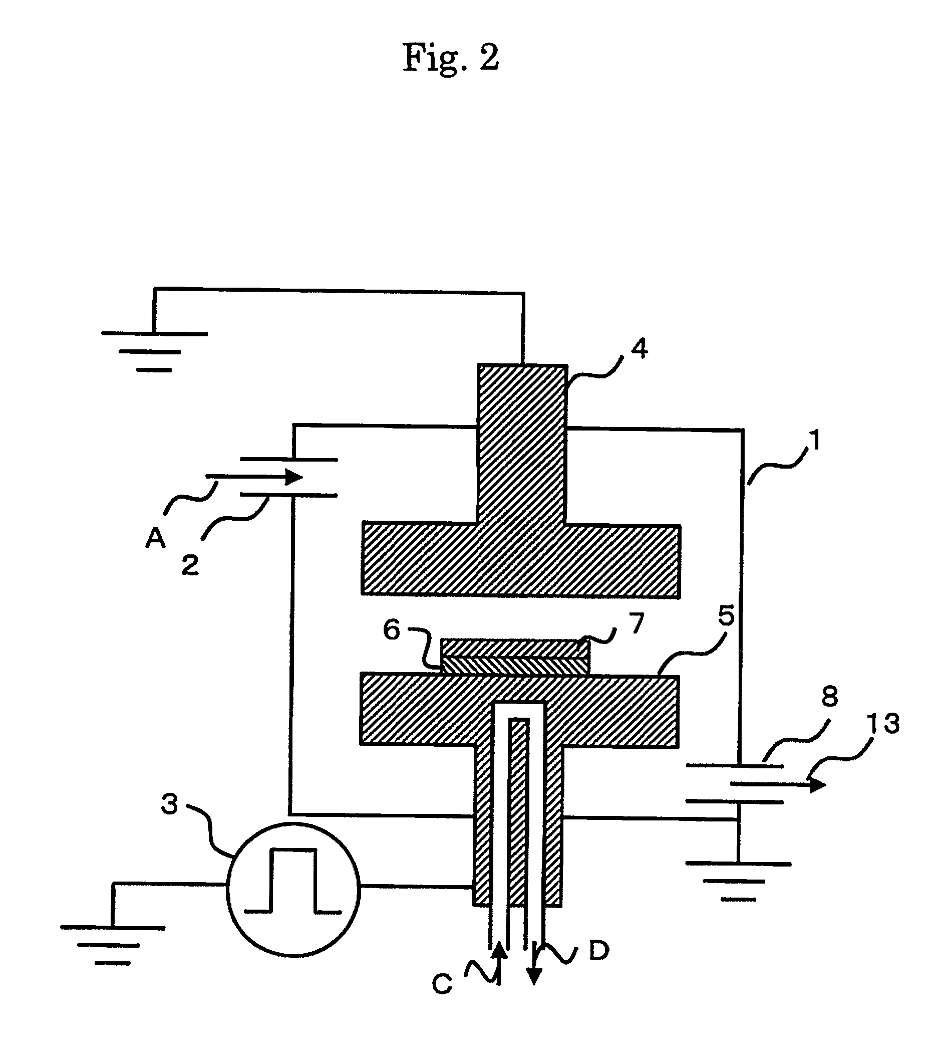
[0112]Using an apparatus as described hereinabove referring to FIG. 2, a thin diamond-like carbon film was produced as mentioned hereinabove. The stainless steel chamber 1 was roughly discoid shape with a chamber height of 300 mm and a diameter Φ of 300 mm. The power source used was a direct-current pulse power source in which an electrostatic induction thyristor device was used.
[0113]The inside of the chamber 1 was evacuated using an oil-sealed rotary pump and an oil-sealed diffusion pump until arrival of the pressure in the inside of the chamber 1 at 1×10⁻² Pa to 1×10⁻³ Pa. Then, acetylene gas was fed to the chamber through a gas supply port until arrival of the pressure within the chamber 1 at 2.6 Pa. Then, a direct-current pulse voltage was applied between the upper electrode 4 and lower electrode 5.
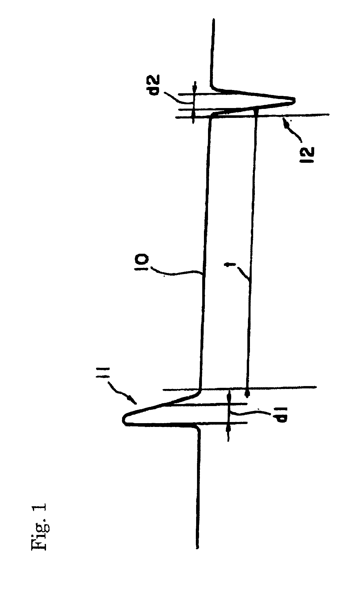
[0114]Here, a positive pulse 11 and a negative pulse 12 were applied alternately and periodically. The crest value of the positive pulse 11 was +10.0 kV, and the crest value of the n...
experiment 3
[0116]Using an apparatus as described hereinabove referring to FIG. 2, a thin diamond-like carbon film was produced as mentioned hereinabove. The stainless steel chamber 1 was roughly discoid shape with a chamber height of 300 mm, and the substrate diameter Φ was 300 mm. The power source used was a power source in which an electrostatic induction thyristor device was used. This power source is the one descried in Japanese Patent No. 3811681B.
[0117]The inside of the chamber 1 was evacuated using an oil-sealed rotary pump and an oil-sealed diffusion pump until arrival of the pressure in the inside of the chamber 1 at 1×10⁻² Pa to 1×10⁻³ Pa. Then, acetylene gas was fed to the chamber through a gas supply port until arrival of the pressure within the chamber 1 at 1.0 Pa. Then, a direct-current pulse voltage was applied between the upper electrode 4 and lower electrode 5.
[0118]Here, a negative pulse 12 alone was applied periodically. The crest value of the negative pulse 12 was −15 kV, a...
PUM
| Property | Measurement | Unit |
|---|---|---|
| Fraction | aaaaa | aaaaa |
| Fraction | aaaaa | aaaaa |
| Fraction | aaaaa | aaaaa |
Abstract
Description
Claims
Application Information
 - Generate Ideas
- Intellectual Property
- Life Sciences
- Materials
- Tech Scout
- Unparalleled Data Quality
- Higher Quality Content
- 60% Fewer Hallucinations
Browse by: Latest US Patents, China's latest patents, Technical Efficacy Thesaurus, Application Domain, Technology Topic, Popular Technical Reports.
© 2025 PatSnap. All rights reserved.Legal|Privacy policy|Modern Slavery Act Transparency Statement|Sitemap|About US| Contact US: help@patsnap.com