Non-contact condensation detecting method and non-contact condensation detecting apparatus

a detection method and condensation technology, applied in the direction of instruments, liquid/fluent solid measurement, specific gravity measurement, etc., can solve the problems of inability to perform precise measurement, affecting the measurement of the temperature sensor located downstream, and excessive heat conducted to the inner walls of the flow path, so as to accurately predict dew condensation and transpiration. , to achieve the effect of efficiently preventing dew condensation and accurate prediction

Inactive Publication Date: 2008-06-26
RICOH KK
View PDF9 Cites 36 Cited by
  • Summary
  • Abstract
  • Description
  • Claims
  • Application Information

AI Technical Summary

Benefits of technology

[0046]Accordingly, the present invention may provide a detector element, a non-contact condensation detecting method, and a non-contact condensation detecting apparatus in which the above-described disadvantage is eliminated.
[0047]A preferred embodiment of the present invention provides a detector element that can capture (detect) three-dimensional heat diffusion with a three-dimensional temperature sensor, capture a three-dimensional isothermal line with the temperature sensor, make the distance between a heating unit and the temperature sensor shorter than the distance between the heater and a substrate, and engage in a phenomenon in a three-dimensional space including heat elements.
[0048]A preferred embodiment of the present invention provides a non-contact condensation detecting method and a non-contact condensation detecting apparatus that can detect gas aggregation and transpiration on the surface of a measurement subject from a remote location in a non-contact manner based on physical changes in the atmosphere that is a continuous space in contact with the measurement subject without mounting a dew condensation sensor directly onto the subject object, and quickly detect the state of dew condensation on the surface of the subject object so as to accurately predict dew condensation on the surface of the subject object.
[0049]A preferred embodiment of the present invention provides a recording sheet deformation preventing method and an image forming apparatus that can detect, in real time, the transpiration speed of moisture included in a recording sheet on which an image is to be formed, predict with high precision whether the recording sheet will deform by curling, etc., due to rapid drying, and prevent deformation of the recording sheet, by employing the non-contact condensation detecting apparatus according to the present invention.
[0054]According to one embodiment of the present invention, it is possible to detect states of dew condensation on the object surface in a non-contact manner, accurately predict dew condensation and transpiration on the object surface, and efficiently prevent dew condensation.

Problems solved by technology

However, the following difficulties are faced according to Patent Document 1.
However, as the flow path is a solid object having higher heat conductivity than that of the fluid, excessive heat is conducted to the inner walls of the flow path due to the narrowed shape.
As a result, the temperature sensor receives heat conduction components from the flow path, and a precise measurement cannot be performed.
This also affects the measurement of the temperature sensor located downstream.
Thus, as the distance between the substrate becomes shorter, interference from the substrate increases.
In addition, it is difficult to measure fluid of high viscosity, and at a temperature where the viscosity increases.
However, the heater and the temperature sensor are arranged adjacent to each other on the same plane, and the heat from the heater at the upstream side diffuses three-dimensionally toward the downstream side, and therefore, the temperature sensor can only capture a single plane component of the diffused heat components.
As a result, the conveyance efficiency of heat and sensitivity is low, such that a low-noise, high resolution signal processing circuit is required.
However, this structure is used as a contact point in variable capacitors and magnet coils, and is not intended for a heater and temperature sensor in a heat transportation mechanism.
Conventionally, dew condensation has been a problem in various devices.
Specifically, elements made of materials having high specific heat, and devices of large mass cannot adjust to rapid changes in the temperature / humidity in the surrounding environment.
Therefore, dew condensation occurs on the surface, which causes malfunction of the device.
Dew condensation on the surfaces of these elements significantly affects functions of devices.
Moisture and gas adhering on recording sheets in electrophotographic image forming apparatuses significantly affect the image quality.
Deformation needs to be prevented, because conveyance failures may occur while the sheet is being conveyed.
If dew condensation water is formed on the porous side, the pores are blocked, and permeability to water vapor deteriorates.
A VTR rotatable cylinder device has large heat capacity and dew condensation is thus likely to occur.
Due to dew condensation, magnetic tape may adhere to the rotatable cylinder and get tangled.
When the temperature is near the dew point, where the relative humidity rises, the relative humidity sensor is under a highly humid environment and is likely to maintain moisture, which makes it difficult to predict ice accretion.
In performing this operation, if water droplets are retained on the dew condensation sensor for a long time, the material of the sensor deteriorates.
If the dew condensation sensor is attached like a generic sensor, it cannot detect dew condensation.
Moreover, there are restrictions in attaching the dew condensation sensor to the rotatable cylinder, because of functions of a magnetic head and electrical signals received by the rotatable member.
As a result, precision of detection deteriorates, because the sensor detects a different temperature from that of the atmosphere of the subject of condensation.
The non-contact temperature measuring apparatus disclosed in Patent Document 9 is capable of measuring the temperature of a remote object in a non-contact manner by measuring the temperature gradient of gas; however, gas-liquid phase changes cannot be measured by this method.
However, these dew condensation sensors cannot detect whether dew condensation has occurred on the actual subject.
Therefore, the dew condensation sensors cannot detect dew condensation of the subject by simply being attached to the subject, or being disposed near the subject.
Accordingly, these sensors can only be applied to specific devices, and cannot be used universally.
However, the emissivity differs according to surface conditions, and therefore, an accurate temperature cannot be measured.
Specifically, the direct cause of the deformation is the speed of drying.
Thus, as described in Patent Documents 10, 12, it is difficult to predict deformation such as curling of a recording sheet with high precision, even by detecting the amount of moisture included in the recording sheet.

Method used


Image

  • Non-contact condensation detecting method and non-contact condensation detecting apparatus
  • Non-contact condensation detecting method and non-contact condensation detecting apparatus
  • Non-contact condensation detecting method and non-contact condensation detecting apparatus

Examples


first embodiment

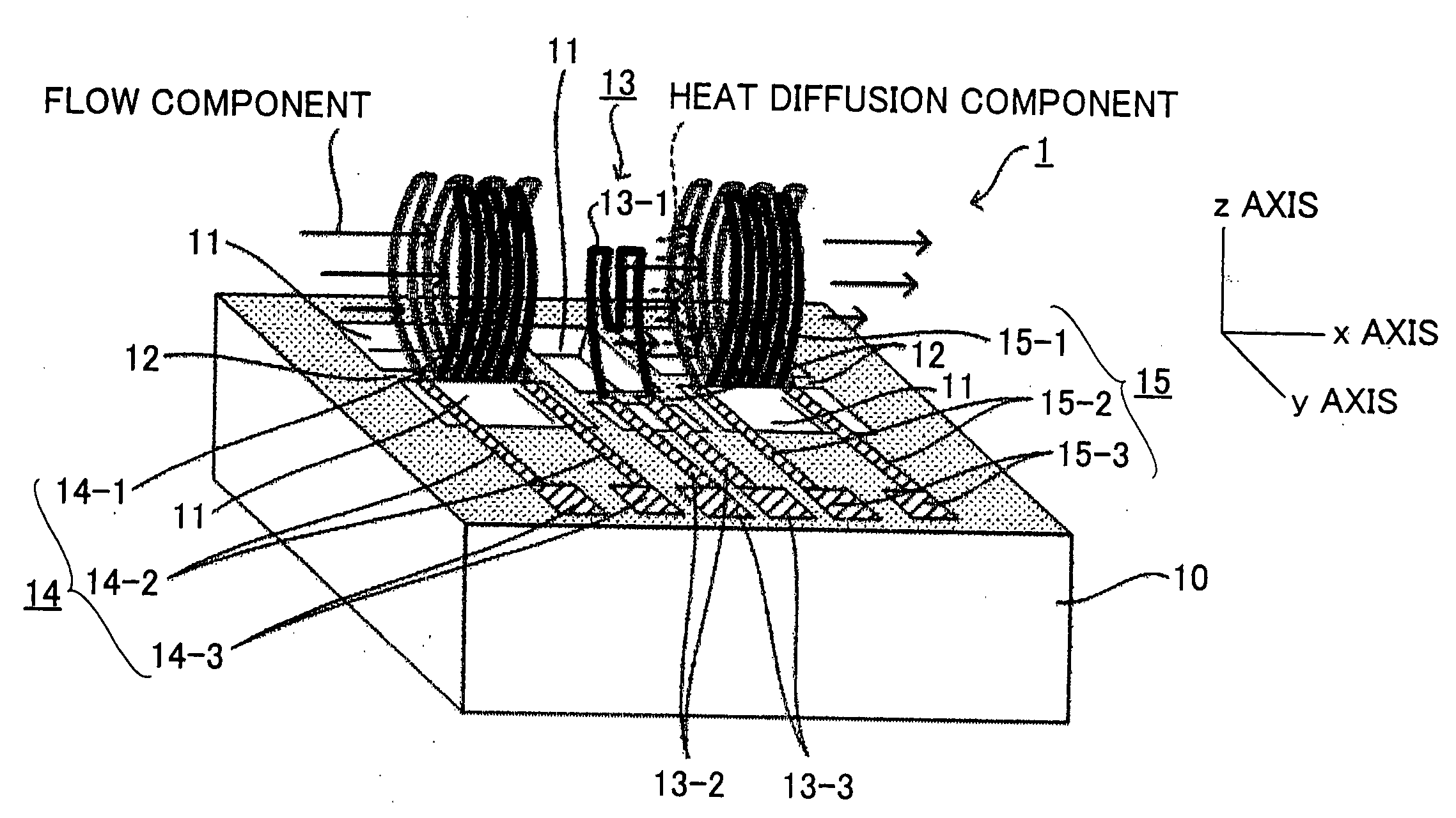
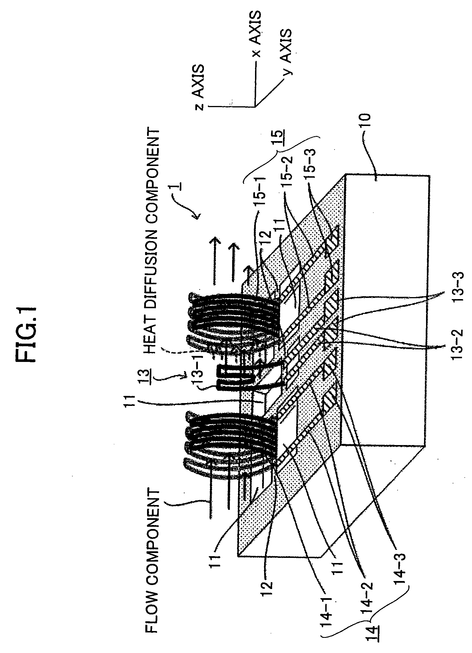
[0111]FIG. 1 is a perspective view of a configuration of a detector element 1 according to the present invention. The detector element 1 includes a substrate 10, bridges 12 disposed across voids 11 in the substrate 10, a heating unit 13, and two temperature sensors 14, 15 disposed on the bridges 12, respectively. The two temperature sensors 14, 15 are disposed in parallel one on each side of the heating unit 13. The temperature sensors 14, 15 include temperature sensor electrodes 14-1, 15-1, respectively, which are shaped like the curved surface of a pipe, and are arranged facing each other. The heating unit 13 includes a heat generating electrode 13-1 connected to power supply leads 13-2. An electrode pad 13-3 is connected to each power supply lead 13-2. The heating unit 13 generates Joule heat using power supplied from the electrode pads 13-3. Further, detection leads 14-2, 15-2 are connected to the ends of the temperature sensor electrodes 14-1, 15-1 of the temperature sensors 14...

third embodiment

[0122]A method of fabricating the detector element 3 is described with reference to FIGS. 9 and 10. FIGS. 9 and 10A are plan views, and FIG. 10B is a cross-sectional view taken along line C-C′ of FIG. 10B. Elements corresponding to those in FIG. 1 are denoted by the same reference numbers.

[0123]As shown in FIG. 9, the heating unit 13 overlaps the temperature sensors 14, 15, and therefore, the heating unit 13 is to be formed by using a sacrifice layer, in a subsequent step after the temperature sensors 14, 15 are formed. First, patterns made of conductive material films are formed on the substrate 10 for the temperature sensor electrodes 14-1, 15-1, the detection leads 14-2, 15-2, and the electrode pads 14-3, 15-3 of the temperature sensors 14, 15, respectively. A metal material having a high resistance temperature coefficient such as Pt, W is used for the heating unit 13 and the temperature sensors 14, 15. Next, patterns made of, for example, Ni, are formed in areas to become the h...

fifth embodiment

[0127]A method of fabricating the detector element 5 is described with reference to FIGS. 14, 15A, and 15B. FIG. 14 and FIG. 15A are plan views, and FIG. 15B is a cross-sectional view taken along line F-F′ of FIG. 15A. As shown in FIG. 14, patterns made of conductive material films are formed on the substrate 10 for the temperature sensor electrode 50-1 of the temperature sensor 50, the detection leads 50-2, the heat generating electrode 51-1 and the power supply leads 51-2 of the heating unit 51, and the electrode pads 50-3, 51-3. As shown in FIGS. 15A, 15B, the insulating layer in the area corresponding to the temperature sensor electrode 50-1 of the temperature sensor 50 and the heat generating electrode 51-1 of the heating unit 51 on the substrate 10 are removed by etching. The temperature sensor 50 and the heating unit 51 are partly detached from the lower layer, forming cantilevered structures. The temperature sensor 50 and the heating unit 51 then form curved surfaces due to...


PUM

PropertyMeasurementUnit
volumeaaaaaaaaaa
volumeaaaaaaaaaa
distanceaaaaaaaaaa

Abstract

A disclosed detector element includes a substrate including a void, a heating unit including a heat generating electrode bridged across the void, and a temperature sensor including a temperature sensor electrode provided above the void. The heat generating electrode and the temperature sensor electrode are warped, cantilevered, and standing up in space. The temperature sensor measures heat quantity transported from the heating unit. Distribution of an atmosphere surrounding an object surface with respect to the object surface, and the transportation state of the atmosphere are measured by using at least one of temperature, humidity, a direction or velocity of flow, pressure, and composition of gas in the atmosphere. Behavior of the gas adhering and aggregating onto the object surface, and behavior of aggregated liquid undergoing transpiration from the object surface are detected, based on the distribution and the transportation state measured.

Description

BACKGROUND OF THE INVENTION[0001]1. Field of the Invention[0002]The present invention relates generally to non-contact condensation detecting methods and non-contact condensation detecting apparatuses, and more particularly to a non-contact condensation detecting method and a non-contact condensation detecting apparatus to easily detect dew condensation.[0003]2. Description of the Related Art[0004]Conventionally, there are methods of measuring the flow velocity and the flow rate of a fluid, and components and density of an atmosphere by detecting heat transported by the fluid and heat propagating in the atmosphere. A sensor serving as a detecting unit in a thermal flowmeter is configured as follows. A heater serving as a heat generation source is arranged on an upstream side of a flow of gas, and a temperature sensor is arranged on a downstream side of the flow of gas. The sensor measures the flow velocity and the flow rate based on the heat quantity (amount of temperature change) c...

Claims


Application Information

Patent Timeline
Patent Type & Authority Applications(United States)
IPC IPC(8): G01N31/00G01N5/02
CPCG01N25/66G01F1/684
Inventor MANAKA, JUNJINAGAI, KAZUTOSHI
Owner RICOH KK
Why Eureka
Try Eureka