
Surface Plasmon Resonance and Quartz Crystal Microbalance Sensor

a surface plasmon resonance and quartz crystal technology, applied in the field of sensors, can solve the problems of low signal/noise ratio, low spr measurement sensitivity compared to prism-coupler spr sensors, and the detection limitation of spr is approximately 1 ng/cm, so as to achieve the effect of improving or overcoming

Inactive Publication Date: 2008-07-10
AGENCY FOR SCI TECH & RES +1
View PDF6 Cites 31 Cited by
  • Summary
  • Abstract
  • Description
  • Claims
  • Application Information

AI Technical Summary

Benefits of technology

[0158]In the disclosed sensor embodiments, SPR resonation is based on the incidence of laser beams from the back of the sensor chip via the prism, no penetration of light needs to pass into the tested solution and the sensitivity region for the specific substance is restricted to the extension length of an evanescent wave, i.e. the depth of an electromagnetic wave penetrating into the liquid medium from the sensing surface side. Consequently, there will be minimum of influence on the response connected to specifically bound analyte molecules from non-bound sample molecules. More over, as described above, the sensitivity of the SPR devices based on the ATR prism coupler is much higher than the SPR sensors using grating couplers.
[0159]It will be appreciated that the disclosed sensor embodiments do not rely on grating structures for coupling to quartz substrates. Accordingly, the SPR measurement of the disclosed embodiments do not rely on the incidence of light beams through the sample solutions. It is not therefore necessary for the sample undergoing analysis in the present disclosed embodiments to be optically transparent.
[0160]The disclosed sensor embodiments produce SPR and QCM signals with a lower signal / noise ratio compared to grating couplers.

Problems solved by technology

The detection limitation of SPR is approximately 1 ng / cm2.
This has the disadvantage of the results having a low signal / noise ratio.
Moreover the SPR measurement sensitivity is low compared to prism-coupler SPR sensors.

Method used


Image

  • Surface Plasmon Resonance and Quartz Crystal Microbalance Sensor
  • Surface Plasmon Resonance and Quartz Crystal Microbalance Sensor
  • Surface Plasmon Resonance and Quartz Crystal Microbalance Sensor

Examples


example 1

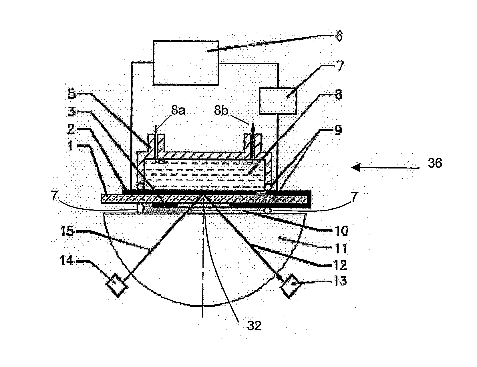
[0125]In example 1, SPR and QCM measurements were generated using the same sensor system arrangement as described above with reference to FIG. 3. Accordingly, the sensor system arrangement for this example will be described with reference to FIG. 3 using the same reference numerals.

[0126]Simultaneous SPR and QCM measurements were obtained using gold-coated quartz disks as the substrate. The ATR SPR was generated from the electrode 2 on the first side of the quartz substrate 1. The QCM oscillation was driven by the application of an AC voltage over the quartz substrate 1 through the electrodes (2,3). For ATR SPR excitation, an index matching liquid in the form of index matching toluene (10) was sealed between O-rings (7). Toluene is an electrically non-conductive and has low viscosity and low density relative to water. The index matching toluene acts as a passive light coupling interface for excitation of surface plasmon resonance.

[0127]In this example, the substrate 1 is a 6 MHz AT-...

example 2

[0131]In example 2, the same sensor chip 30′ of FIG. 5 was utilised in an AUTOLAB ESPIRIT™ SPR instrument that is commercially available from Eco Chemie B.V. of Utrecht, The Netherlands. Accordingly, the sensor chip 30′ for this example will be described with reference to FIG. 5 using the same reference numerals.

[0132]In this example, 10 MHz quartz substrate 1′ having a thickness of 0.166 mm was placed on the hemispherical prism 11′ with a supporting slide 24′. The supporting slide 24′ Index matching liquid 10′ was injected into the cavity 15a′.

[0133]FIG. 10b shows the angular scan curves obtained from the sensor chip measured with the Autolab SPR instrument. The Autolab SPR instrument uses a laser diode at a wavelength of 670 nm and a vibrating mirror to modulate the angle of incidence of the p-polarized light beam on the substrate. A full description of the method of generating the SPR is disclosed in Ward et al, Anal. Biochem. 2000, 285, 179, which is incorporated herein for ref...

example 3

[0136]In this example, QCM oscillation behaviors (oscillation quality and stability) were studied when one face of the quartz substrate was exposed to an aqueous solution and the other face of the quartz substrate the index matching liquid.

[0137]Bovine Serum Albumin (BSA) adsorption on QCM was measured using a 10 MHz, AT-cut quartz substrate from International Crystal Manufacturers Inc of Oklahoma City, Okla., United States of America having a thickness of 0.166 mm and a diameter 13.66 mm. Both sides of the quartz were deposited with 100 nm thick gold electrode, the diameter of electrodes were 5 mm and there were no openings on any electrodes.

[0138]For in-situ frequency measurement in liquid, the QCM crystals were fixed into two plexiglas blocks with neoprene O-ring seals. The upper face of the quartz formed the base of an open liquid cell and the lower face forms the base of a closed liquid cell. The open cell allowed application liquid up to 1 mL and the closed liquid cell was abo...


PUM


Abstract

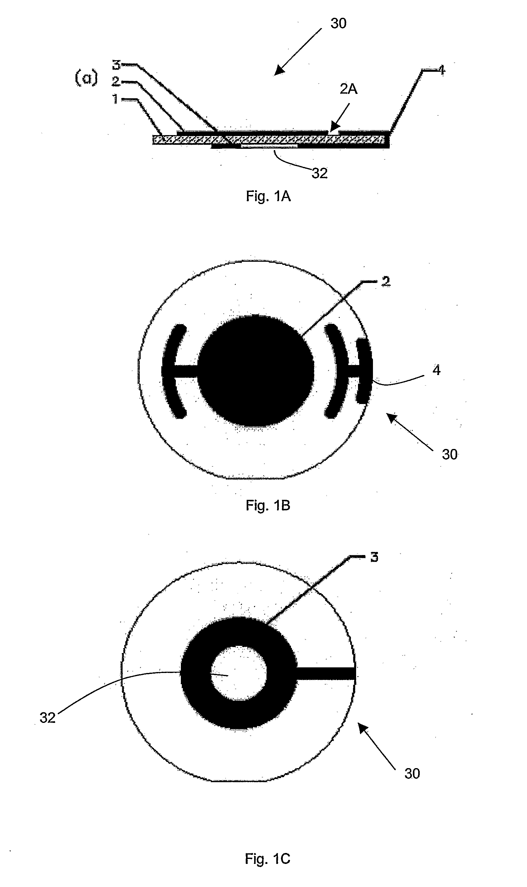
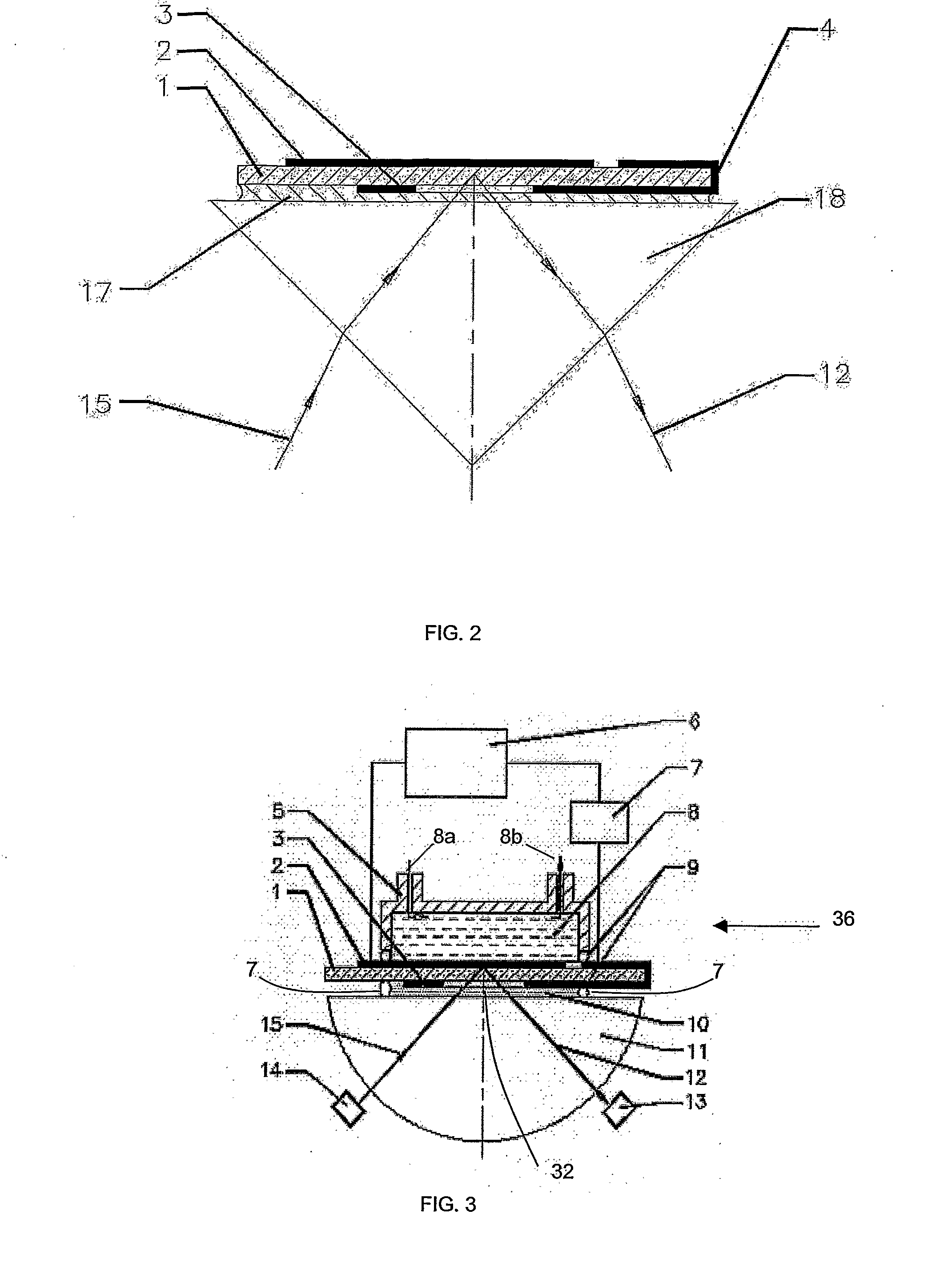
A sensor chip assembly for use in a sensor capable of Surface Plasmon Resonance (SPR) and gravimetric sensing. The assembly comprising a transparent piezoelectric substrate (I) having a first surface and a second surface opposite to the first surface. The assembly also comprising first and second thin film metal electrodes (2,3) respectively provided on the first and second surfaces of the substrate (1). The second thin film metal electrode (3) being position on the second surface of the substrate (1) such that a light beam is capable of being transmitted through the second surface of the substrate and reflected from the first thin film metal electrode. The assembly also comprising an attenuated total reflection (ATR) coupler (11) disposed adjacent to the second thin film metal electrode (3).

Description

TECHNICAL FIELD[0001]The present invention generally relates to a sensor for sensing a biological, biochemical or chemical sample. More particularly, the present invention relates to a sensor that is capable of sensing a biological, biochemical or chemical sample using Surface Plasmon Resonance and microgravimetric sensing techniques.BACKGROUND[0002]Surface Plasmon Resonance (SPR) and Microgravimetric sensing techniques, such as Quartz Crystal Microbalance, are known independently as methods suitable for in-situ, label free sensing and analysis of binding reactions. Sensors using SPR or QCM have been used to analyse biological, biochemical and chemical samples.[0003]QCM devices comprise a quartz crystal wafer having two planar metal electrodes disposed on the two surfaces of the wafer. The sample to be analysed is adsorbed onto the surface of one of the electrodes. The shift in the quartz crystal can be excited to mechanical resonance by an alternating an electric field due to the i...

Claims


Application Information

Patent Timeline
IPC IPC(8): G01G3/16G01N21/41G01N29/12G01N21/55H01L41/053
CPCG01N5/02G01N21/553G01N29/022G01N2291/0422G01N2291/0256G01N2291/02818G01N2291/0421G01N2291/0255
Inventor WANG, GUANGYUSU, XIAODIKNOLL, WOLFGANGWU, YING-JU
Owner AGENCY FOR SCI TECH & RES
Learn More