Manufacture and measuring of automotive components
Inactive Publication Date: 2008-08-14
BURGESS NORTON MFG
View PDF3 Cites 7 Cited by
Summary
Abstract
Description
Claims
Application Information
AI Technical Summary
This helps you quickly interpret patents by identifying the three key elements:
Problems solved by technology
Method used
Benefits of technology
Benefits of technology
[0009]In a preferred method of manufacturing an automotive component in accordance with the present invention, a low alloy constituent, low hardenability material is utilized that accordingly requires a more aggressive cooling or quenching operation to produce a strong martensitic wear resistant hard structure. The preferred method includes the traditional powdermetallurgy operation of die compacting and sintering that is followed by a quenching operation wherein the sintered material is quenched in an environment of a cooling rate that results in a metallic microstructure that is 50-80% martensitic, 20-50% bainitic with a small portion of fine pearlite, generally less than 10%. Quenching may include other quench methods than atmospheric. Because this material does not have high relative hardenability and transform as readily to martensite at a quench rate between 1.9° F. and 5.5° F. per second, untempered martensite is not formed by localized hot spots in the operation of the automotive component. Because there is almost no untempered martensite in the metallic microstructure, resulting from high localized temperatures fracture initiation sites are sufficiently reduced. The service life of the automotive transmission or clutch brake component such as a backing plate is greatly extended. Further, the resulting micro structure from reduction in hardenability reduces the material's propensity to crack propagation in the finished component.
Problems solved by technology
Further, the resulting micro structure from reduction in hardenability reduces the material's propensity to crack propagation in the finished component.
Method used
Image
Click on the blue label to locate the original text in one second.
Reading with bidirectional positioning of images and text.
Examples
example 1
[0033]In a method of manufacturing an automotive clutch component, an initial pre alloymetal powder of particle sizes between 250 and 1 micron was provided comprising, by weight, 0.45% nickel, 0.65% molybdenum, with the balance essentially iron.
[0034]An additional 0.7% graphite, and 1.75% coppermetal powder of particle sizes between 150 and 1 micron, by weight, were admixed to form an admixed metal powder.
[0035]0.5% EBS was added as a lubricant to form a lubricated admixed metal powder.
[0036]The lubricated, admixed metal powder was compacted at a pressure of 45 tons per square inch.
[0037]The die compacted metal blank was then placed on a machined flat ceramic support and sintered at a temperature 2050° F. for 15 minutes.
[0038]The sintered metal blank was then quenched while on the ceramic support metal blank at a rate of 5.4° F. (3.00° C.) per second from an initial temperature of (2000° F.) (1090° C.) to a temperature of (500° F.) (260° C.) per use. The quenched was then tempered...
example 2
[0041]In a method of manufacturing an automotive clutch component, an initial pre alloy metal powder of particle sizes between 250 and 1 microns was provided comprising, by weight, 0.45% nickel, 0.65% molybdenum, with the balance essentially iron.
[0042]An additional 0.9% graphite, and 1.75% copper metal powder of particle size between 150 and 1 micron, by weight, were admixed to form an admixed metal powder.
[0043]0.5% EBS was added as a lubricant to form a lubricated admixed metal powder.
[0044]The lubricated, admixed metal powder was compacted at a pressure of 45 tons per square inch.
[0045]The die compacted metal blank was then placed on a ceramic support and sintered at a temperature 2050° F. for 15 minutes.
[0046]The sintered metal blank was then quenched while on the ceramic support at a rate of 1.9° F. (1.05° C.) per second from an initial temperature of (2000° F.) (1090° C.) to a temperature of (500° F.) (260° C.) per use. The quenched metal blank was then tempered at a temperat...
example 3
[0049]In a method of manufacturing an automotive clutch component, an initial pre alloy metal powder of particle size between 250 and 1 micron was provided comprising, by weight, 0.45% nickel, 0.65% molybdenum, with the balance essentially iron.
[0050]An additional 0.9% carbon, and 1.75% copper metal powder of particle size between 150 and 1 micron, by weight, were admixed to form an admixed metal powder.
[0051]0.5% EBS was added as a lubricant to form a lubricated admixed metal powder.
[0052]The lubricated, admixed metal powder was compacted at a pressure of 45 tons per square inch.
[0053]The die compacted metal blank was then placed on a machined flat ceramic support and sintered at a temperature 2050 for 15 minutes.
[0054]The sintered metal blank was then quenched while on the ceramic support at a rate of 1.9° F. (1.0° C.) per second from an initial temperature of (2000° F.) (1090° C.) to a temperature of (500 ° F.) (260° C.) per use. The quenched metal blank was then tempered at a te...
PUM
Property
Measurement
Unit
Temperature
aaaaa
aaaaa
Fraction
aaaaa
aaaaa
Fraction
aaaaa
aaaaa
Abstract
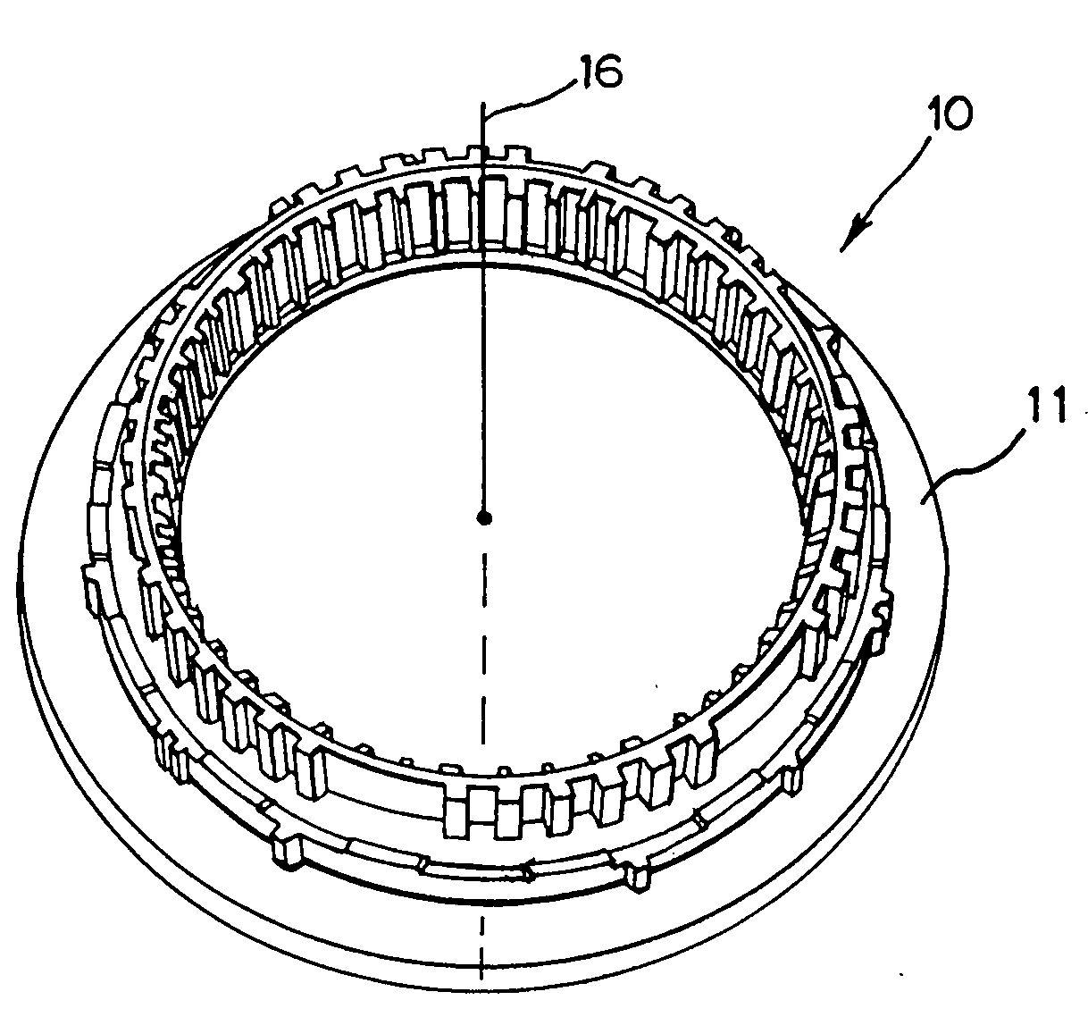
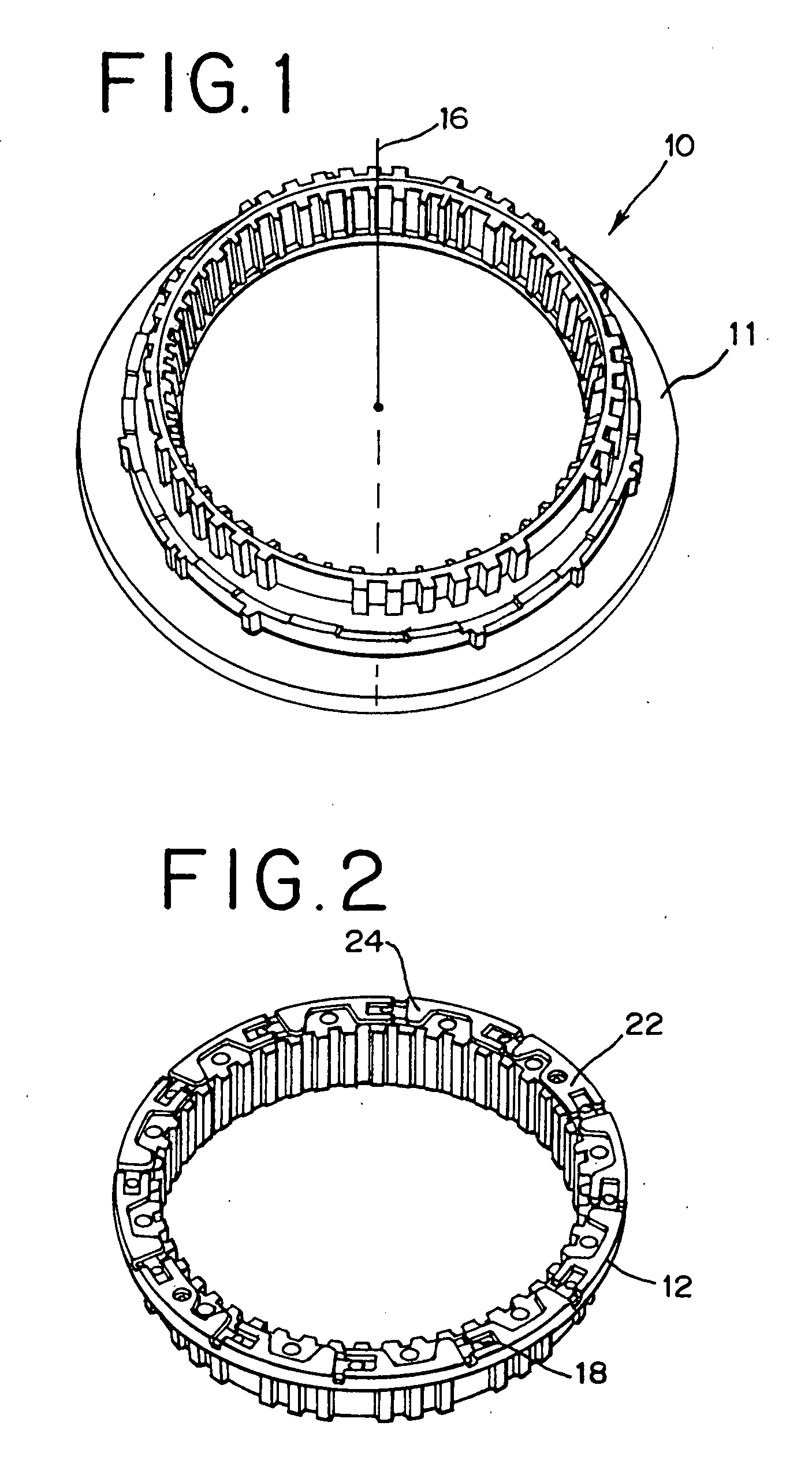
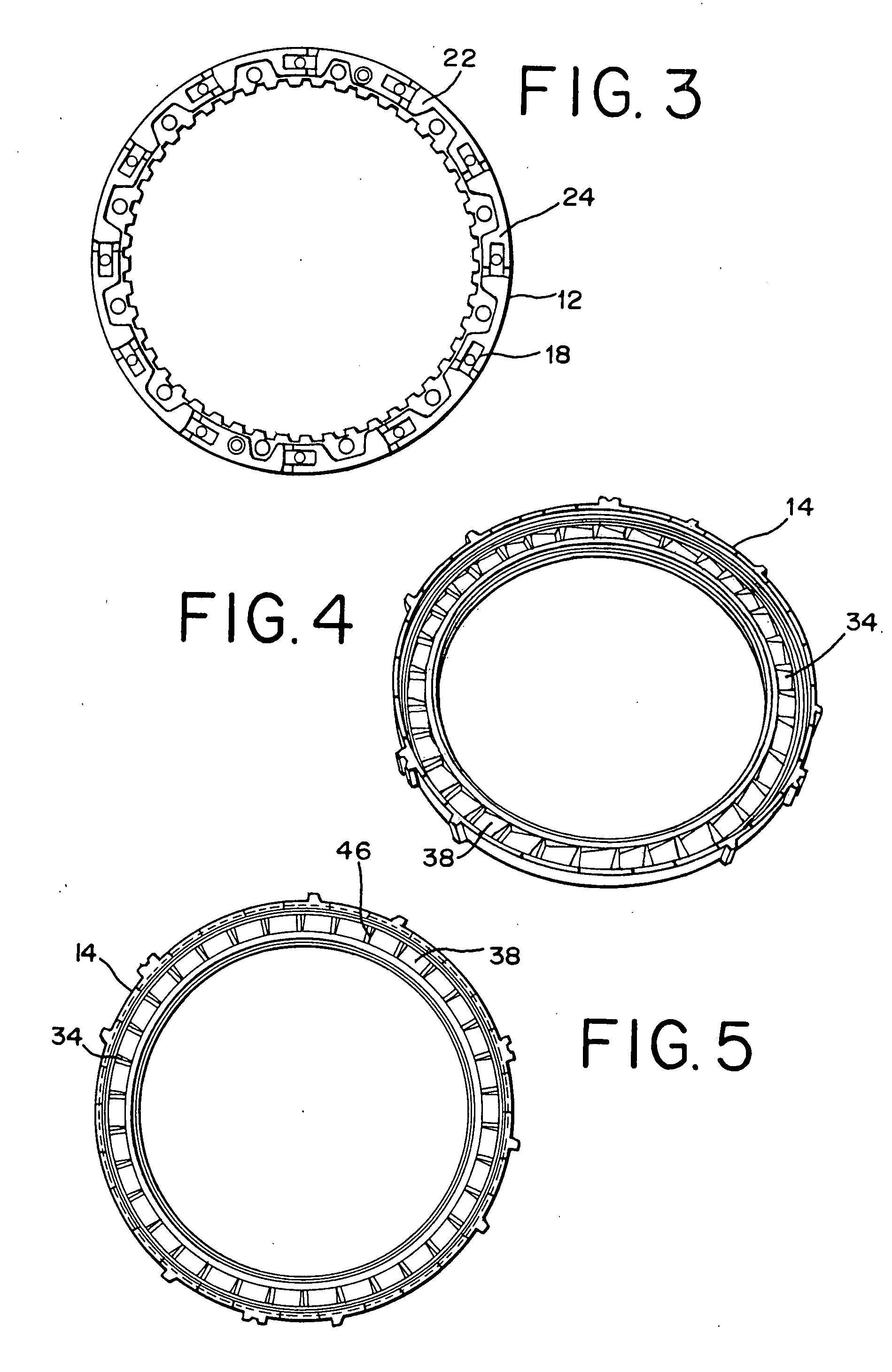
Clutch components for automotive use usually include a pair of clutch members with operative faces. In particular, planar one way clutches include a pair of clutch members whose operative faces are enclosed spaced opposition, with each clutch face including a plurality of recessed defining respective load bearing shoulders. A plurality of struts are disposed between the coupling face of the members, and such struts are moveable between the coupling position and non coupling position. A preferable method of manufacturing such clutch components includes powdermetal operations comprising die compacting a metalpowder into a metal blank, placing the die compacted metal blank in a machined flat ceramic support, sintering the metal blank to form a sintered metal blank, and cooling the sintered metal blank to form a cooled metal blank. The preferred metallic structure of the cooled metal blank is 50-80% martensite and 20-50% bainite and fine pearlite. The cooled metal blank is then measured for flatness, roundness or perpendicular structure in a measuring devise having supports and probes. Signals from the probes are analyzed to determine whether the parameters of concern are within tolerance.
Description
BACKGROUND OF THE INVENTION[0001]The present invention relates to automotive clutch or transmission components and, more particularly, to so called one way clutches wherein one or more struts provide a mechanical coupling between opposed clutch faces and a pair of coaxially rotateable members, with a method for manufacturing and measuring such components.[0002]As explained in U.S. Pat. No. 6,571,926, in such one way clutches, a driving member engages a driven member.[0003]The manufacture of such automotive components is set forth in pending U.S. patent application Ser. No. 11 / 585,297 filed Oct. 23, 2006, and assigned to the assignee of the present application.[0004]A thin flat strut is carried within each of the driving members' pockets such that a first longitudinal end may readily engage and bear against the shoulder defined by the corresponding recess in the driving member. The struts second, opposite longitudinal end is urged by spring force toward and against the driven member,...
Claims
Application Information
Patent Timeline
Application Date:The date an application was filed.
Publication Date:The date a patent or application was officially published.
First Publication Date:The earliest publication date of a patent with the same application number.
Issue Date:Publication date of the patent grant document.
PCT Entry Date:The Entry date of PCT National Phase.
Estimated Expiry Date:The statutory expiry date of a patent right according to the Patent Law, and it is the longest term of protection that the patent right can achieve without the termination of the patent right due to other reasons(Term extension factor has been taken into account ).
Invalid Date:Actual expiry date is based on effective date or publication date of legal transaction data of invalid patent.

