Process for Manufacturing an Electrochemical Device

Inactive Publication Date: 2008-09-25
PIRELLI & C
View PDF3 Cites 4 Cited by
  • Summary
  • Abstract
  • Description
  • Claims
  • Application Information

AI Technical Summary

Benefits of technology

[0010]The Applicant has perceived that a key-point for manufacturing electrochemical devices with reliable and efficient performance lies in providing cathode, anode and/or electrolyte membrane based

Problems solved by technology

Nanosize powders are expensive and difficult to prepare in large quantities.
However, besides its simplicity, this technique has clear disadvantages because it provides large grain size (1-10 μm) and requires multiple repetitions of prolonged thermal treatment and grinding.
As a consequence, uncontrolled crystalline growth might occur which causes chemical and dimensional non-uniformity.
Unfortunately these methods are time consuming if large quantity of fine po

Method used


Image

  • Process for Manufacturing an Electrochemical Device
  • Process for Manufacturing an Electrochemical Device
  • Process for Manufacturing an Electrochemical Device

Examples


Example

EXAMPLE 1

Cerium / Gadolinium Oxides Nanopowder and Ce0.8Gd0.2O1.9

[0053]1.8716 g of Ce(NO3)3.6H2O and 0.4279 g of Gd(NO3)3.6H2O were added to 10 ml H2O while stirring and heating up to 50° C. to provide a solution with a metal cation concentration of 0.538 mol / l. 10 ml of 2-hydroxyethylmethacrylate and 5 ml polyethyleneglicoldiacrylate were added. The solution was heated up to 100° C. 20 drops of 35 vol % H2O2 were added to initiate the gel formation.

[0054]The resulting gel was decomposed at 500° C. for 5 h. 1 g of the title compound was obtained and characterized as follows.

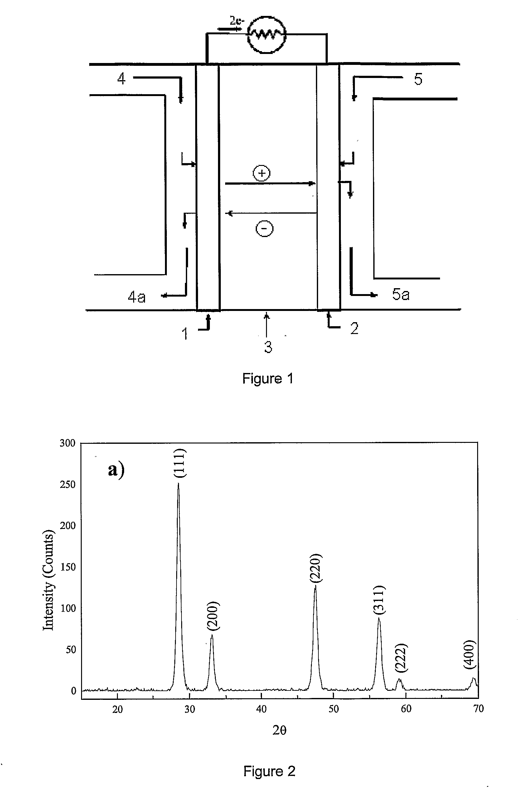
[0055]The XRD pattern of FIG. 2 shows that the sample is monophasic and Ce0.8Gd0.2O1.9 powder has a mean primary grain size of 10 nm calculated using the Debye-Scherrer formula (A. R. West, “Solid State Chemistry and its application” Ed. John Wiley & Sons, 1996, page 174).

[0056]The nanopowder was compacted in pellet under an uniaxial pressure of 200 MPa and sintered at a temperature of 800° C. for 5 hours, then at...

Example

EXAMPLE 2

Copper / Nickel Oxides Nanopowder and Cu0.47Ni0.53 Alloy (1:1 by Weight)

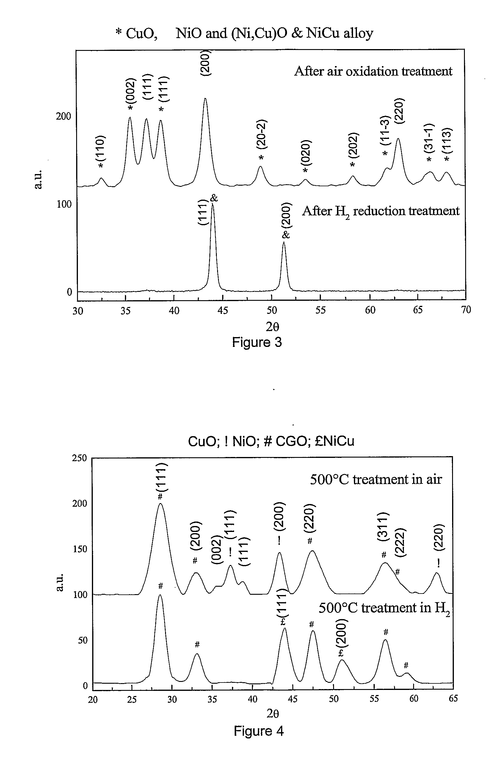
[0058]1 g of Cu was added with 5 ml H2O while stirring and heating up to boiling. HNO3 (3 ml; 65 vol %) was dropwise added, followed by 1 g of Ni. Further HNO3 (3.5 ml; 65 vol %) was added followed by H2O up to a total volume of 10 ml. The resulting solution had a metal cation concentration of 3.277 mol / l. The solution was added with 10 ml of 2-hydroxyethylmethacrylate, 5 ml of polyethyleneglycol diacrylate and 50 mg of AIBN, then heated (80° C.) to yield a gel.

[0059]The gel was dried at 200° C. for 2 h. The resulting xerogel was ground, crashed and decomposed at 500° C. for 2 h to give a mixture of CuO, NiO and Cu0.47Ni0.53O which was characterized as follows.

[0060]FIG. 3 shows the XRD patterns of said mixture. The mean primary grain size was calculated from the XRD patterns by use of the Debye-Scherrer formula (A. R. West “Solid State Chemistry and its application” Ed. John Wiley & Sons, 1996, page 174)...

Example

EXAMPLE 3

Copper / Nickel / Cerium / Gadolinium Oxides Nanopowder and CU0.47Ni0.53 and Ce0.8Gd0.2O1.9 Cermet

[0062]1.164 g of Cu was added with 5 ml of H2O while stirring and heating up to boiling. HNO3 (3.5 ml; 63%) was dropwise added. 1.212 g of Ni was then added followed by HNO3 (63%) up to a total acid volume of 4.3 ml.

[0063]The resulting mixture was added with 5.992 g. of Ce(NO3)3×6H2O, 1.370 g of Gd(NO3)3×6H2O and water up to a total volume of 15 ml to provide a solution with a metal cation concentration of 3.747 mol / l.

[0064]The resulting mixture was added with 15 ml of 2-hydroxyethylmethacrylate, 7.5 ml of polyethyleneglycol diacrylate and 100 mg of AIBN, and heated (80° C.) up to the gel formation.

[0065]The gel was dried at 200° C. for 2 h to yield a xerogel which was ground, crashed and decomposed at 500° C. for 1 h. A powder mixture (6 g) of CuO, NiO, CU0.47Ni0.53O and Ce0.8Gd0.2O1.9 (hereinafter CGO-20) was obtained and characterized as follows.

[0066]FIG. 4 shows the XRD analysis...


PUM


Abstract

Process for manufacturing an electrochemical device including a cathode, an anode and at least one electrolyte membrane disposed between the anode and the cathode, wherein at least one of the cathode, the anode and the electrolyte membrane, contains at least a ceramic material.

Description

BACKGROUND OF THE INVENTION [0001]The present invention relates to a process for manufacturing an electrochemical device comprising at least one component based on a ceramic or ceramic containing material, for example cermets (ceramic and metallic composites), and for preparing nanosize powders for producing said at least one component.[0002]The active basic structure of an electrochemical device such as a solid oxide fuel cell (SOFC) or an oxygen generator consists of an electrolyte layer (electrolyte membrane) interposed between an anode and a cathode. Typically, electrolyte membrane, cathode and anode contain ceramics and / or cermets.[0003]In the present specification and claims, ceramic and cermet materials are collectively referred to as “ceramics” or “ceramic materials”.PRIOR ART [0004]The effectiveness of ceramics in electrochemical devices depends upon the characteristics of the powders used as starting materials which are used to produce bulk ceramic products. In general, to...

Claims


Application Information

Patent Timeline
IPC IPC(8): C01F17/00C01F11/02C01G37/02C01G25/02C01G27/02C01G23/04C01F7/02C01D1/02C01G30/00C01B35/08C01G11/00C01G53/04C01G51/04C01G3/02C01G5/00C01G7/00C01G15/00C01G45/02C01G47/00C01G41/02C01G39/02C01G31/02C01G33/00C01G35/00C01F15/00C01G19/02C01G43/01C01B13/18C01B13/32H01M4/88H01M8/12
CPCB82Y30/00C01B13/18C01B13/185C01P2004/62Y02E60/525H01M4/9066H01M8/1253H01M8/126Y02E60/522C01P2004/64Y02E60/50Y02P70/50
Inventor SIN XICOLA, AGUSTINDUBITSKY, A. YURIALBIZZATI, ENRICOKOPNIN, EVGENYRODA, ELENA
Owner PIRELLI & C
Why Eureka
Try Eureka