Fibrous 3-Dimensional Scaffold Via Electrospinning For Tissue Regeneration and Method For Preparing the Same

a 3-dimensional, tissue regeneration technology, applied in the direction of prosthesis, application, drug composition, etc., can solve the problems of destroying or contracting the scaffold, the strength of the natural polymer is so poor, and the use of the fibrous matrix scaffold is not common

Inactive Publication Date: 2008-09-25
EWHA UNIV IND COLLABORATION FOUND
View PDF3 Cites 22 Cited by
  • Summary
  • Abstract
  • Description
  • Claims
  • Application Information

AI Technical Summary

Benefits of technology

[0018]FIGS. 2, 3 and 4 illustrate examples of the fibrous porous scaffolds of the invention which are 3-12 in diameter, which is the size of between nanofiber (1-500 nm) and microfiber (30-50 ). The scaffold of the invention has as small fiber diameter as possible to provide large surface area for successful cell adhesion and proliferation and at the same time a regular form and strength to enhance 3-dimensional tissue re-generation capacity.
[0022]The fibrous porous scaffold of the present invention has the size of between nanofiber and microfiber, preferably 1-15 < in diameter, and a regular form and strength under a proper pressure to help 3-dimensional tissue regeneration and at the same time to provide a large surface area for cell adhesion, so that it can be effectively used for adhesion and proliferation of such cells as endothelial cells, skin cells and osteocytes. In addition, the scaffold of the invention can be simply prepared by using electrospinning without wasting of polymers or drugs, so it can be more efficient than any other method.

Problems solved by technology

However, the fibrous matrix scaffold is not commonly used today as its disadvantages have been confirmed as follows; a scaffold composed of natural polymer has so poor strength in water phase that it might be destroyed or contracted to lose its original form, and even a synthetic polymer scaffold cannot secure a room with its fibrous structure alone, so that it ends in the membrane shaped 2-dimensional structure rather than 3-dimensional structure.
So, such scaffolds having only 2-dimensional structure are limited in applications since it is very difficult with these scaffolds to envelop a medicine and regulate its release or to employ a natural polymer with high physiological activity.
However, it is a problem of this method that the remaining salts or rough surfaces cause cell damage (Mikos et al., Biomaterials, 14: 323-330, 1993; Mikos et al., Polymer, 35: 1068-1077, 1994).
However, the above methods are also limited in producing open cellular pores (Wang et al., Polymer, 36: 837-842, 1995; Mooney et al., Biomaterials, 17: 1417-1422, 1996).
However, this method has also a problem of difficulty in cell culture because the size of the produced pore is too small (Lo et al., Tissue Eng. 1: 15-28, 1995; Lo et al., J. Biomed. Master. Res. 30: 475-484, 1996; Hugens et al., J. Biomed. Master. Res., 30: 449-461, 1996).
The above mentioned methods are to prepare a 3-dimensional polymer scaffold which is capable of inducing cell adhesion and differentiation, but using a bio-degradable polymer for the production of a 3-dimensional scaffold for tissue re-generation has still a lot of problems to be overcome.
A polymer scaffold prepared by using electrospinning has been evaluated, but re-sultingly confirmed that it ends up in 2-dimensional membrane structure, which means it is very difficult to use this scaffold as a 3-dimensional structured implantation material with successful cell adhesion (Yang et al., J. Biomater. Sci. Polymer Edn., 5:1483-1479, 2004; Yang et al., Biomaterials, 26: 2603-2610, 2005).

Method used


Image

  • Fibrous 3-Dimensional Scaffold Via Electrospinning For Tissue Regeneration and Method For Preparing the Same
  • Fibrous 3-Dimensional Scaffold Via Electrospinning For Tissue Regeneration and Method For Preparing the Same
  • Fibrous 3-Dimensional Scaffold Via Electrospinning For Tissue Regeneration and Method For Preparing the Same

Examples


example 1

Preparation of a Polymer PLLA Fiber

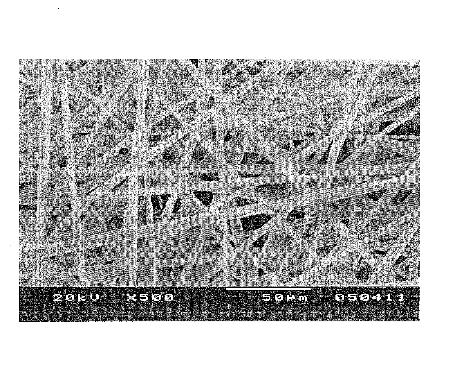
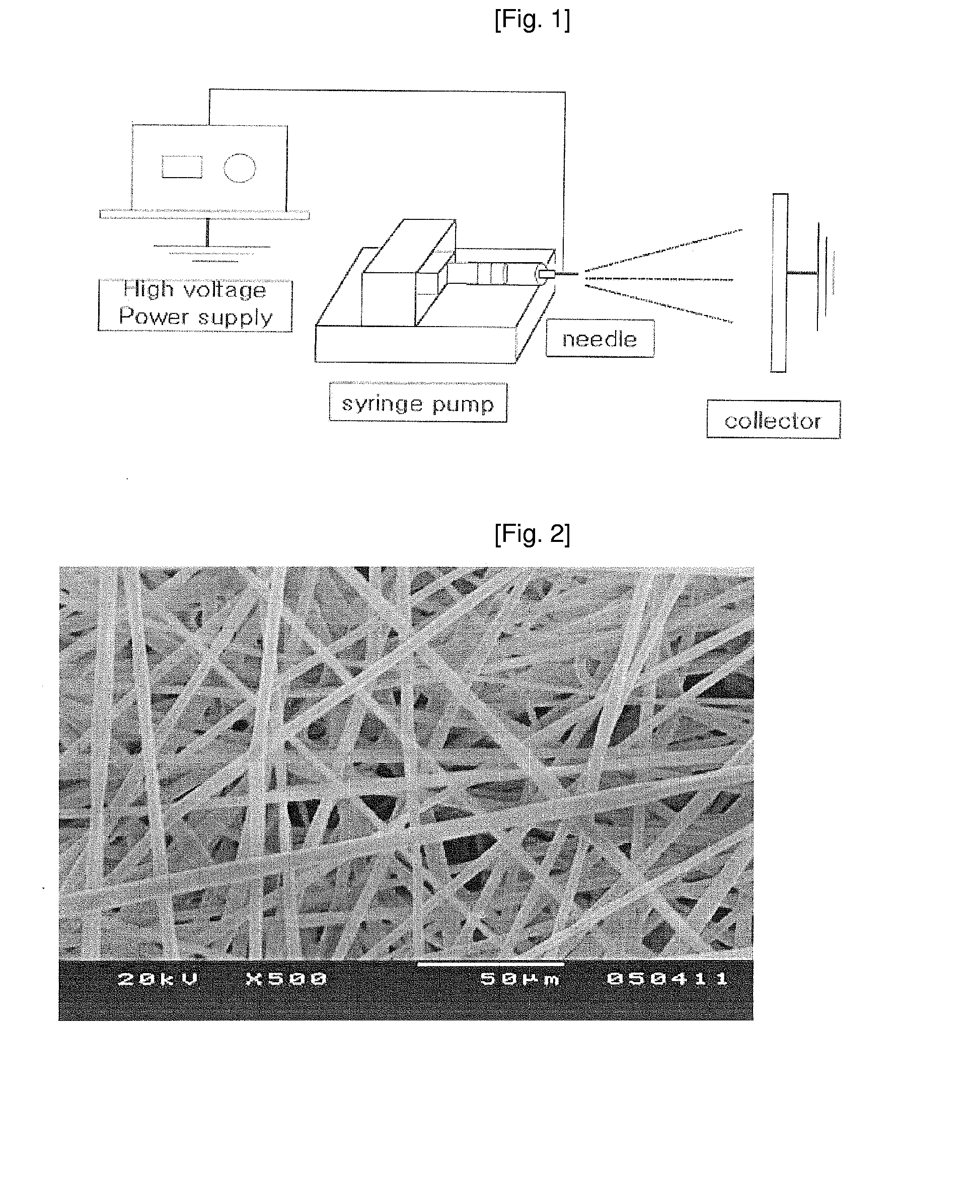
[0048]A PLLA polymer was dissolved in 10 < of dichloromethane solution, resulting in a 5-10% spinning solution. A fiber was prepared from the spinning solution by electrospinning (FIG. 1).

[0049]As an electro-spinner, DH High Voltage Generator (CPS-40KO3VIT, Chungpa EMT, Korea) was used and the details of the electrospinning process are illustrated with the reference to FIG. 1.

[0050]The 5-10% polymer PLLA solution (spinning solution) was filled in a spinning solution depository, which was a 10 < glass syringe. A needle with blunt tip, which is 0.5-1.2 mm in diameter, was used. The releasing speed of the spinning solution was adjusted to 0.060 ml / min. Voltage was set at 10-20 kV and the electric field distance was adjusted to 10-20 cm. It was important for the entire solvent to be volatilized before the drip of the solution on a collector to prepare a target fiber. Thus, the temperature and humidity had to be carefully regulated; the optimum temper...

example 2

Preparation of a Low Molecular PLLA Fiber

[0053]A low molecular PLLA was dissolved in 10 < of dichloromethane solution, resulting in a 14-20% spinning solution. A fiber was prepared from the spinning solution by electrospinning (FIG. 1).

[0054]As an electro-spinner, DH High Voltage Generator (CPS-40KO3VIT, Chungpa EMT, Korea) was used and the details of the electrospinning process are illustrated with the reference to FIG. 1.

[0055]The 14-20% low molecular PLLA solution (spinning solution) was filled in a spinning solution depository, which was a 10 < glass syringe. A needle, which is 0.5-1.2 mm in diameter, was used. The releasing speed of the spinning solution was adjusted to 0.060 ml / min. Voltage was set at 10-20 kV and the electric field distance was adjusted to 10-20 cm. It was important for the entire solvent to be volatilized before the drip of the solution on a collector to prepare a target fiber. Thus, the temperature and humidity had to be carefully regulated; the optimum t...

example 3

Preparation of a Spinning Solution using Dichloromethane and 1,1,1,3,3,3-hexafluoroisopropylpropanol

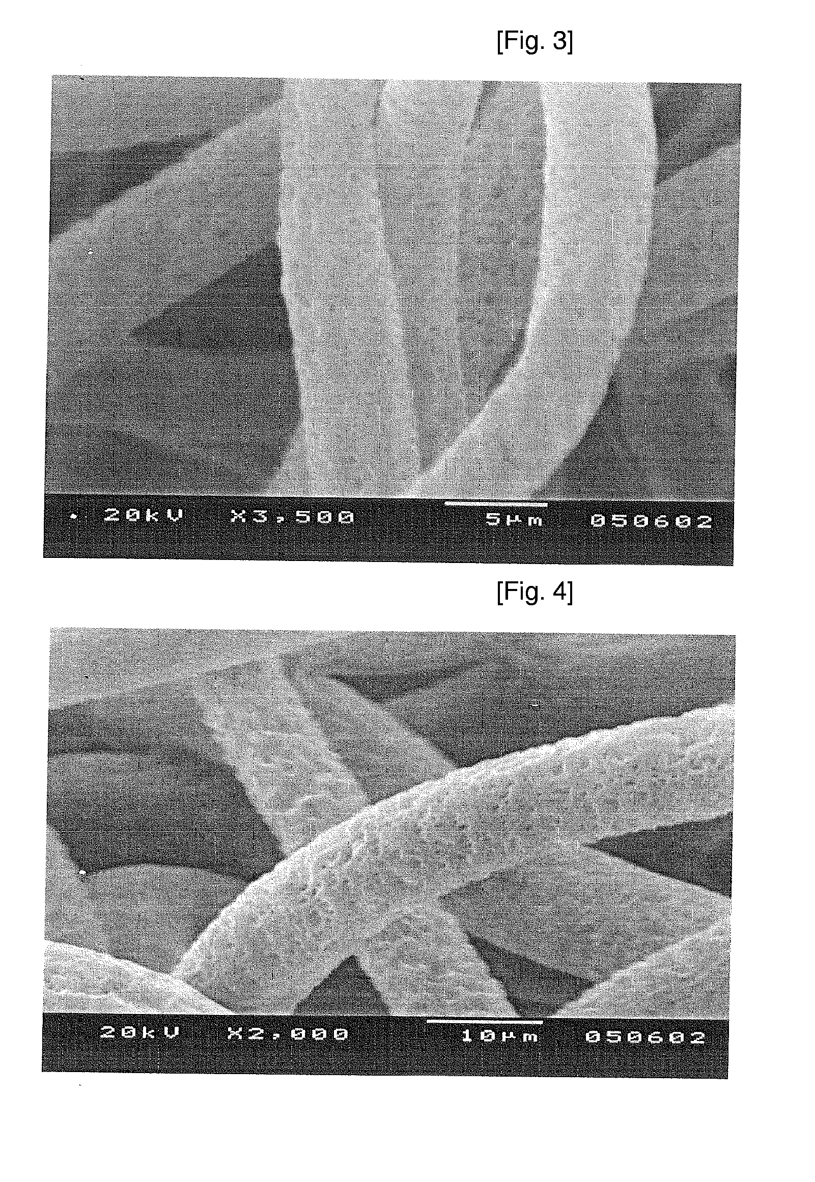
[0058]To dichloromethane was added 1,1,1,3,3,3-hexafluoroisopropylpropanol by 2% of the total solvent, resulting in dichloromethane solution. Then, polymer and low molecular PLLA were dissolved in the dichloromethane solution to prepare a spinning solution with proper concentrations of the polymer and low molecular PLLA. A fiber was prepared from the spinning solution by electrospinning. The resultant fiber was proved to be very stable in shape and spun at a wide range of temperature and humidity (possibly spun even at 30° C. with 50% humidity). The obtained polymer was confirmed to be 1-10 < in diameter. The addition of 1,1,1,3,3,3-hexafluoroisopropylpropanol caused the fiber to be thinner and more stable spinning, but at the same time, increased electrostatic force between fibers and formed a shield-like membrane.


PUM

PropertyMeasurementUnit
boiling pointaaaaaaaaaa
sizeaaaaaaaaaa
inner diameteraaaaaaaaaa

Abstract

The present invention relates to a fibrous 3-dimensional porous scaffold via electrospinning for tissue regeneration and a method for preparing the same. The fibrous porous scaffold for tissue regeneration of the present invention characteristically has a biomimetic structure established by using electrospinning which is efficient without wasting materials and simple in handling techniques. The fibrous porous scaffold for tissue regeneration of the present invention has the size of between nanofiber and microfiber and regular form and strength, so that it facilitates 3-dimensional tissue regeneration and improves porosity at the same time with making the surface area contacting to a cell large. Therefore, the scaffold of the invention can be effectively used as a support for the cell adhesion, growth and regeneration.

Description

TECHNICAL FIELD [0001]The present invention relates to a fibrous 3-dimensional porous scaffold via electrospinning for tissue regeneration and a method for preparing the same.BACKGROUND ART [0002]Tissue regeneration is induced by supplying cells or drug loaded matrix when tissues or organs lose their functions or are damaged. At this time, a scaffold for tissue regeneration has to be physically stable in the implanted site, has to be physiologically active to control regeneration efficacy, has to be easily degraded in vivo after generating new tissues and must not produce degradation products with toxicity.[0003]The conventional scaffolds for tissue regeneration have been produced by using polymers having a certain strength and form, for example sponge type or fibrous matrix or gel type cell culture scaffold has been used.[0004]The conventional fibrous matrix scaffold has open cellular pores and the pore size is enough size that cells are easily adhered and proliferated. However, th...

Claims


Application Information

Patent Timeline
Patent Type & Authority Applications(United States)
IPC IPC(8): A61K9/00C12N5/06A61K35/12A61P43/00
CPCA61L27/48D01D5/003A61L27/56A61P9/00A61P17/00A61P19/00A61P43/00A61L27/14A61L27/20A61L27/40B82Y5/00
Inventor LEE, SEUNG JINHAN, SOLSHIM, IN KYONG
Owner EWHA UNIV IND COLLABORATION FOUND
Why Eureka
Try Eureka