Fabrication method for drug-eluting stent with medicine-compatible loading mechanisms

a technology of loading mechanism and stent, which is applied in the field of mems-based (microelectricalmechanical system), can solve the problems of unsatisfactory stent fabrication method, inability to reduce the cost of manufacturing while enhancing the design capability of stent, and inability to meet the requirements of stent size and thickness, and achieves fine pitch and high versatility

Inactive Publication Date: 2008-10-16
HUANG JUNG TANG
View PDF6 Cites 25 Cited by
  • Summary
  • Abstract
  • Description
  • Claims
  • Application Information

AI Technical Summary

Benefits of technology

[0014]The present invention is to provide a MEMS technology to mass produce a seamless drug-eluting stent capable of loading such numerous drug-coated mechanisms as micro-holes, micro-caves, or micro-trenches. This novel manufacturing method easily combines nano technologies to elute any bio-compatible anti-thrombosis drugs, making drug-eluting stent low cost, high versatility, and fine pitch. By using three major processes including a multi-layers photolithography process, a multi-layers electroforming process, and a subtle polishing process gives to fabricate sophisticated drug-eluting stents in mass production.
[0015]The advantages of low cost, fine pitch, and varied shapes benefit from the multi-layers photolithography process, by which it gives the benefit of fabricating future much thinner and finer stents as combined with a micro-electroforming process.
[0016]Unlike some given traditional manufacturing processes to stent, this invention is unnecessary to use the spot welding process to bond the both ends of the stent together. Furthermore, costing less money in manufacturing and designing, the present invention could dramatically avoid the occurrence of any defects or material deformation resulted from high temperature in the spot welding process.
[0018]In addition to giving a lower manufacturing cost contributed by a mass production, this process is easy to carry any drug-loading mechanisms such as micro-holes, micro-caves, or micro-trenches for bio-compatible anti-thrombosis to prevent the recurrence of clogged and narrowed blood vessels by releasing the coated drug on the stent.

Problems solved by technology

Partly because it needs to request to a higher budget to purchase laser cutting machining equipment and partly because the grid density of the stent is naturally limited to the laser spot size, this process is almost impossible to cut the cost in manufacturing while enhance design capability for stent in shapes or profiles.
The ion sputtering process, in essence, is not ideal for stent fabrication due to far lower deposition rate.
That is, this proposed method has difficult dealing with a stent in higher thickness or a substrate in larger size.
However, this process adopting an additional process or we call it a secondary manufacturing step to fabricate the drug-loading mechanism, trenches, rather than fabricate them simultaneously with the main structure of the stent may lead to a higher cost and more complicated manufacturing procedure.
How to accurately position the micro-syringes to the drug-loading areas to fill them up with drug is not an easy task.
What's more, the two ends of the stent seamed by using a spot welding process is liable to cause an excessive concentration of stress on the welding joints, which might badly damage the connected blood vessel and reduce the bio-compatible ability between the implanted stent and the wall of the stent.
The method is similar to U.S. Pat. No. 7,135,038 B1, both of which increase their process complexity since they require using an extra process to form the drug-loading areas.
In conclusion, adopting an additional process or a secondary process to form the drug-loading mechanisms like micro-holes, micro-caves or micro-trenches would not only increase process complexity but also add manufacturing cost.
By comparison, some traditional stent manufacturing methods like etching or sputtering generally rely on the spot welding process to bond the both ends of the stent together, making much smaller and finer stents impossible.

Method used


Image

  • Fabrication method for drug-eluting stent with medicine-compatible loading mechanisms
  • Fabrication method for drug-eluting stent with medicine-compatible loading mechanisms
  • Fabrication method for drug-eluting stent with medicine-compatible loading mechanisms

Examples


Embodiment Construction

[0025]Referring to the attached drawings, a preferred embodiment of the fabrication method for drug-eluting stent with medicine-compatible loading mechanism will be fully understood in detail as follows:

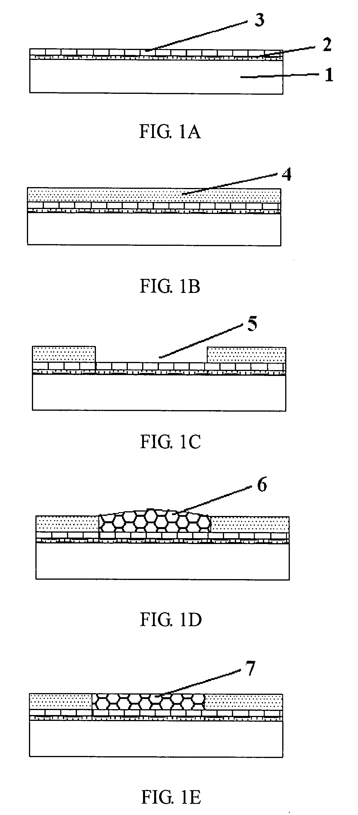
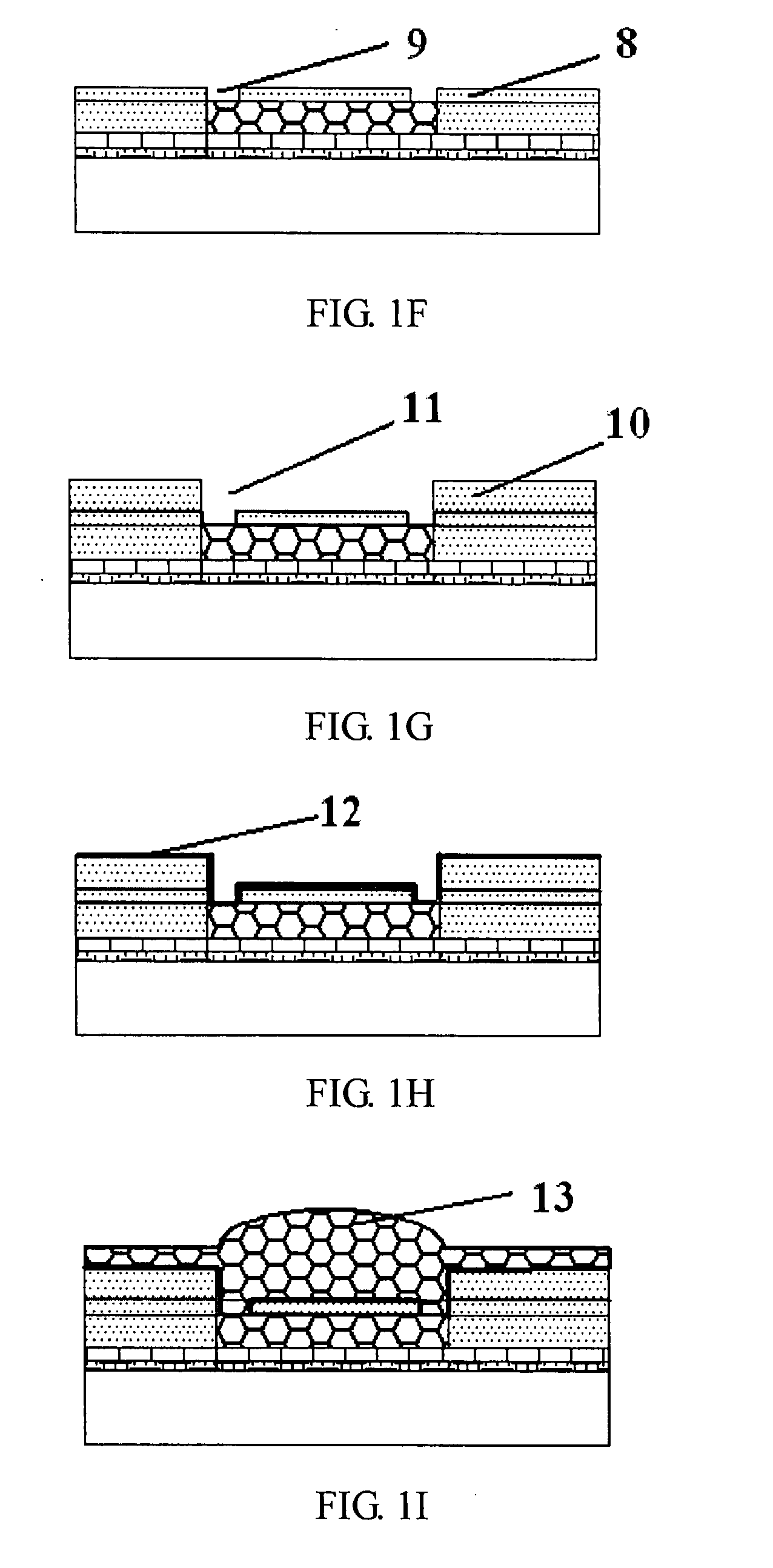
[0026]Referring to FIGS. 1A-1M, these drawings particularly present the schematic sectional diagrams step by step for the drug-eluting stent process.

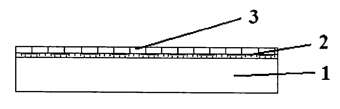
[0027]Referring to FIG. 1A, firstly, two metallic layers, Cr 2 and Cu 3, are evenly coated over the substrate 1 as two UBMs by sputtering, evaporation or other deposition techniques. Other metals such as Ti (Titanium), W (Tungsten), Ni (Nickel) and Au are also available to be used as these two UBM layers.

[0028]Referring to FIG. 1B, next, the first PR layer 4 is then coated on the second Cu 3 UBM layer. The first PR layer 4 coating in the photolithography process contains three fundamental operation steps described as follows: (1) prop adequate amount of PR layer 4 on the center of the substrate 1 until the whole substrate 1 is covered at...


PUM

PropertyMeasurementUnit
temperatureaaaaaaaaaa
flow rateaaaaaaaaaa
flow rateaaaaaaaaaa

Abstract

A MEMS-based fabrication process is disclosed to fabricate a hollow seamless drug-eluting stent. This stent fabrication process is characterized by using a photolithography process, a composite electroplating process, and a polishing process to mass-produce drug-eluting seamless stents. Combining a multi-layers photolithography process with a multi-layers composite electroforming process could make the formation of micro-holes, micro-caves, or micro-trenches integrated with this hollow seamless eluting-stent for any anti-thrombosis drug loading or filling.

Description

BACKGROUND[0001]1. Field of Invention[0002]The present invention relates to a MEMS-based (Micro-Electrical-Mechanical System) process used for making a hollow seamless stent, more specifically, relates to a process involving in utilizing a photolithography process, an electroforming process, a polishing process, an electrolytic polishing process, a material shaping process, and a drug immersing or coating process to form a drug-eluting stent. This new drug-eluting process characterizes low-cost, fine-pitch, and mass-production; and in particular, the drug-eluting stent itself could load various micro-trenches, micro-caves, or even micro-holes varying in sizes and types for anti-thrombosis drug eluting.[0003]2. Description of Related Arts[0004]Cardiovascular disease, mostly caused by some disorders such as high blood pressure, diabetes, smoking, high blood fat, and people with a family history of heart disease, is the most common health problem worldwide. In general, the related card...

Claims


Application Information

Patent Timeline
Patent Type & Authority Applications(United States)
IPC IPC(8): A61F2/04A61F2/82
CPCA61F2/82A61F2/91A61F2250/0068
Inventor HUANG, JUNG-TANGCHAO, PEN-SHANHSU, HOU-JUN
Owner HUANG JUNG TANG
Why Eureka
Try Eureka