Micromachined electrowetting microfluidic valve

Active Publication Date: 2008-10-23
MICROPOINT BIOTECHNOLOGIES CO LTD
View PDF14 Cites 33 Cited by
  • Summary
  • Abstract
  • Description
  • Claims
  • Application Information

AI Technical Summary

Benefits of technology

[0018]The present invention also discloses the method to operate the micromachined electrowetting valve by applying electrical voltage across the conducting regions to modulate the affinity of the hydrophobic patch for a fluid. For example, a liquid column can be introduced into a micro-channel under conditions that allow the liquid to flow until it is stopped by surface tension pressures from a large contact angle at a hydrophobic patch surface in the channel. The liquid flow can be restarted by applying an electric voltage across conducting regions adjacent to the hydrophobic regions, electrostatically reducing the contact angle and allowing the fluid to flow.
[0019]Methods of present invention include, e.g., operation of a micromachined electrowetting valve by applying electrical voltage across conducting regions to generate stop bubbles by electrolysis. For example, a method of controlling a flow of a fluid in a channel can include providing a channel comprising an internal surface and a hydrophobic patch disposed upon the surface, providing a first electrically conductive region exposed on the internal surface, flowing a fluid from the first electrically conductive region along the channel toward the hydrophobic patch, and applying an electrolytic voltage to the first electrically c

Problems solved by technology

Compared to conventional devices and techniques, these devices have a much smaller footprint and require minimum amount of resources to gather the same amount of information.
However, many macro-scale valve configurations are incompatible such small devices, and a need remains for micro-scale fluid control valves that can be opened and closed with precision.
This idea was successfully applied to mercury-electrolyte systems, but a major drawback of this idea was electrolytic decomposition or Joule heating of aqueous electrolyte solutions, even when low voltages wer

Method used


Image

  • Micromachined electrowetting microfluidic valve
  • Micromachined electrowetting microfluidic valve
  • Micromachined electrowetting microfluidic valve

Examples


example 1

An Electrowetting Valve

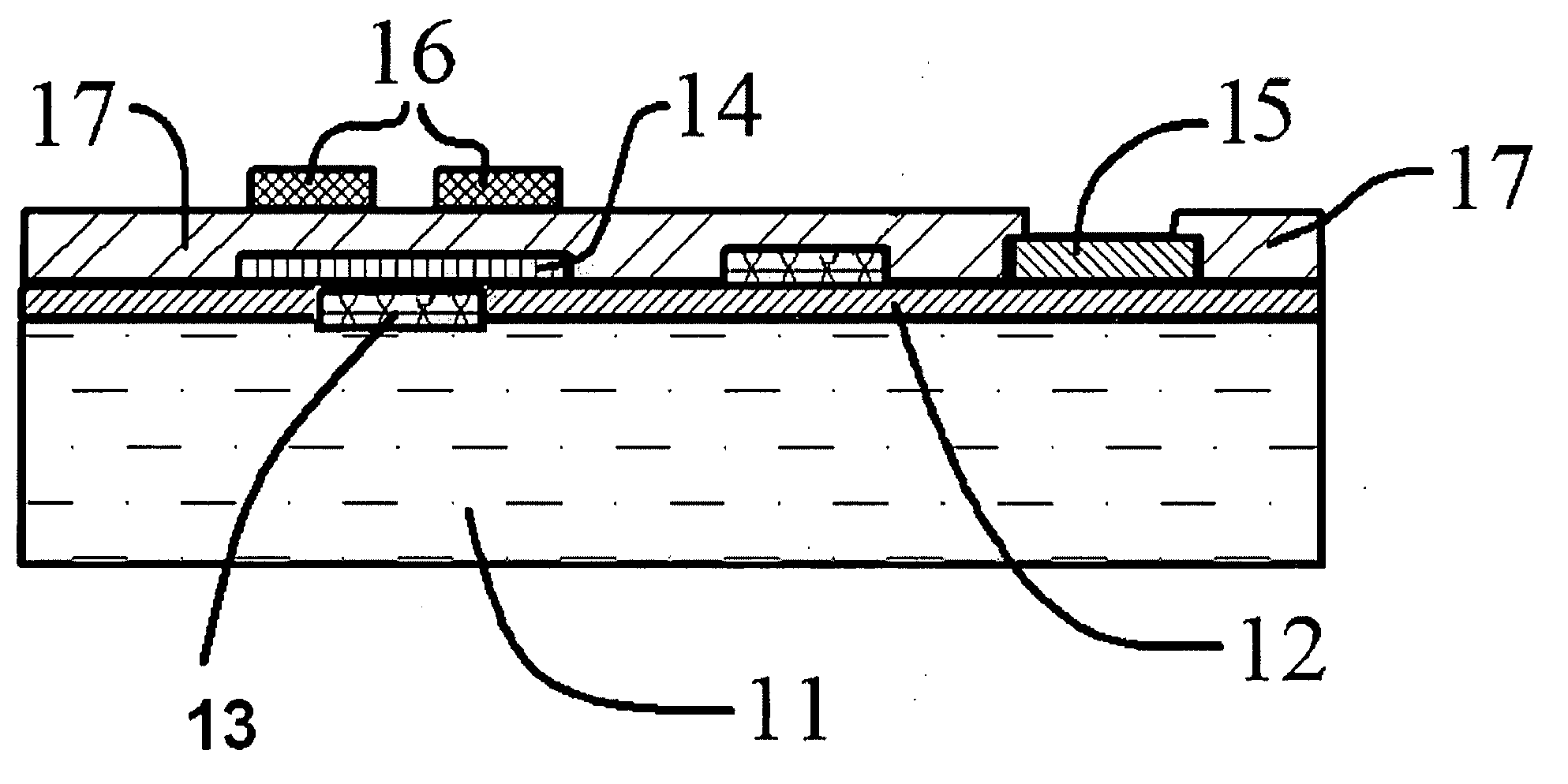
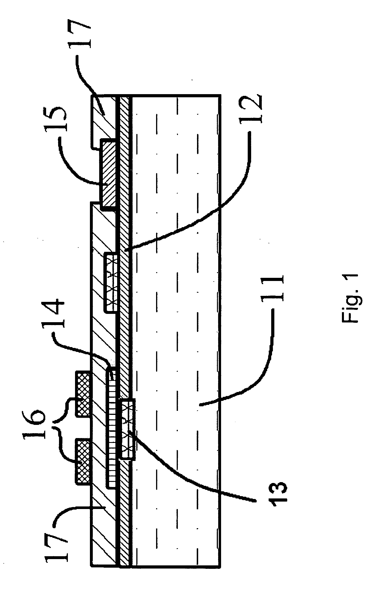
[0065]An electrowetting valve can be provided with a conductive electrode under a hydrophobic patch. FIG. 1 shows a cross-sectional view of a bottom plate 1 for a micromachined microfluidic valve according to one preferred embodiment of current invention. The bottom plate comprises a first dielectric layer 12 deposited on top of the silicon substrate 11. Typically, this first dielectric layer 12 is made of silicon nitride that is deposited on the silicon substrate 11 to serve as an isolation layer from the silicon. Thin metal conducting layers including a first conducting region 14 and a second conducting region 15 can be fabricated on top of the first dielectric layer 12. The conducting regions 14 and 15 are typically made of Au, Pt, or ITO, and are deposited on top of first dielectric layer 12 using Physical Vapor Deposition (PVD) machines commonly available in semiconductor industry. The conducting regions 14 and 15 are patterned with photolithography techn...

example 2

Preferred EW Surface Designs

[0071]The layout and arrangement of conducting regions 14 and 15 can have many different configurations. For example, FIGS. 4 and 5 show optional schemes according to the preferred embodiments of present invention. The size of both electrodes 32 and 31 (associated with conductors 14 and 15, respectively), the separation between electrodes 31 and electrodes 32, and the number of electrodes 31 and 32 all can vary based on the particular application. The hydrophobic patch 16 can optionally cover the areas electrodes 31 and 32 full, or only cover a part of their areas.

[0072]According to another preferred embodiment of present invention, the conducting regions 14 and 15 can be arranged in a scheme as illustrated in FIG. 6. In this figure, the conducting region 14 is not covered by the second dielectric layer 17, and is thus exposed to a fluid flowing in such a micro-channel. To use this scheme, the conducting region 14 can act as a ground electrode when a volt...

example 3

Resetting a Valve

[0073]According to another preferred embodiment of present invention, the electrowetting valve can also be used to stop the fluid flow in the micro channel. FIGS. 8 to 10 schematically illustrate reestablishment of a flow stop condition on a hydrophobic stop gate. In this case, a third conductive region 26 can be employed, as shown in FIG. 8 to provide a second electrically conductive electrode on the surface of the microfluidic channel. In the embodiment of FIG. 8, electrolysis and gas evolution (e.g., H2 and / or O2 from water) can be achieved by applying an electric voltage across conducting regions 14 and 26, resulting in current flow when a conductive fluid traverses the capillary channel between the regions to complete the electric circuit. When an electric voltage E is applied across the conductive regions 14 and 26, with a positive lead of the electric voltage E connected to conductive region 14, as shown in FIG. 8, bubble 25 can be generated, e.g., at the int...


PUM


Abstract

This invention relates to a systems and methods of controlling the flow of a fluid in a capillary or microfluidic channel. A first pair of electrodes can influence the wetting of a fluid front at a relatively hydrophobic surface in the channel. A second pair of electrodes can electrolytically generate a bubble that can stop fluid flow when it contacts the hydrophobic surface. Flow of a fluid in a channel can be stopped on contact with the hydrophobic surface and restarted when an electrostatic field reduces the contact angle of the fluid at the hydrophobic surface. The electrostatic field can be removed and the fluid stopped again when an electrolytically generated bubble contacts the hydrophobic surface to reestablish the blocking contact angle of the fluid, gas and surface.

Description

CROSS-REFERENCE TO RELATED APPLICATIONS[0001]The present application is related to a prior application Ser. No. 11 / 696,401, Micromachined Electrowetting Microfluidic Valve, filed Apr. 4, 2007, by Wang, et al., which was converted to provisional application 60 / 966,533, of which the present application claims benefit of and priority to; and, which application is incorporated herein by reference.FIELD OF THE INVENTION[0002]The present inventions are directed to methods and devices for controlling fluid flows. In particular aspects, the invention includes microfluidic valves that can stop and initiate flows based on control of a contact angle at the fluid / surface interface. The valve can be reset to the stop configuration by introduction of a bubble to generate an new liquid / gas / solid interface.BACKGROUND OF THE INVENTION[0003]Microfluidic devices and “microscopic” fluid handling systems are becoming essential in many important fields. The advantages of fast response times, easy integra...

Claims


Application Information

Patent Timeline
IPC IPC(8): F15C1/06
CPCF15C5/00F16K99/0017F16K99/0051F16K99/0019B01L2400/0688B01L2300/1833B01L2400/0427B01L2400/0442B01L3/502738Y10T137/2196Y10T137/2224
Inventor WANG, MARK Y.WAN, ZHILIANGSURANGALIKAR, HARSHALWU, GUANGHUAATA, ERHAN
Owner MICROPOINT BIOTECHNOLOGIES CO LTD
Why Eureka
Try Eureka