Slectable Multiwavelength Laser for Outputting Visible Light

a laser system and multi-wavelength technology, applied in the direction of laser details, optical resonator shape and construction, basic electric elements, etc., can solve the problems of lithium iodate having limited utility in high-power applications, unable to optimise the position of that crystal, and substantial beam displacement due to refraction when the crystal is refraction

Inactive Publication Date: 2008-10-23
MACQUARIE UNIV
View PDF6 Cites 63 Cited by
  • Summary
  • Abstract
  • Description
  • Claims
  • Application Information

AI Technical Summary

Benefits of technology

[0046]The method may further comprise a step of providing an intracavity etalon. The intracavity etalon may prevent generation of parasitic laser wavelengths. The oscillation of these parasitic wavelengths with the fundamental may be the cause of very high laser fields (spiking) that surpass the damage threshold of the laser optics. The step of providing an intracavity etalon is particularly relevant to flashlamp pumped Q-switched cavities although an intracavity etalon may be used in all cavities.

Problems solved by technology

This limitation is a significant disadvantage, as the laser of the invention is limited to the output frequencies obtainable using lithium iodate, since it is rare to find crystals capable of performing both of these functions together.
A further disadvantage is that, since the lithium iodate crystal serves two discrete functions, it is not possible to optimise the position of that crystal independently for two functions.
Yet a further disadvantage is that lithium iodate has limited utility in high power applications, since it has a relatively low damage threshold.
Yet another disadvantage is that, since the laser of the prior art requires a reasonably long Raman crystal (in order to obtain sufficient gain), and this Raman crystal needs to be rotated in order to achieve phase matching, there will be substantial beam displacement due to refraction when the crystal is off normal incidence.
This means that the cavity of the prior art will need to be significantly realigned for each wavelength, which thus greatly reduces the utility of the laser of the prior art.

Method used


Image

  • Slectable Multiwavelength Laser for Outputting Visible Light
  • Slectable Multiwavelength Laser for Outputting Visible Light
  • Slectable Multiwavelength Laser for Outputting Visible Light

Examples


example 1

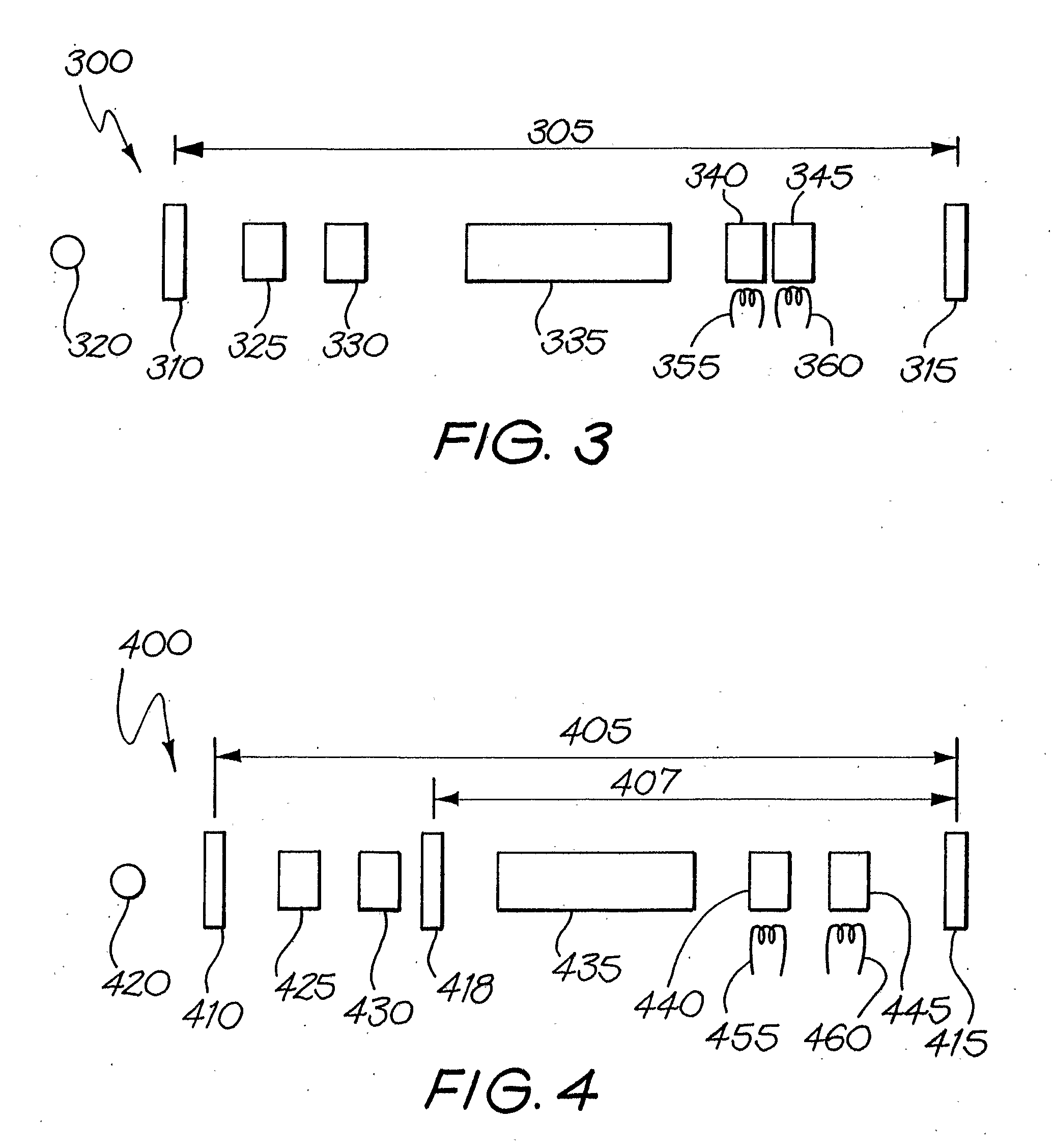
[0215]FIG. 5 shows an experimental setup for a selectable laser system 500 according to the present invention. In FIG. 5, a bent cavity 510 is defined by a reflective face 515 on a laser material 535 and reflectors 520 and 525. The reflective face 515 is transmissive at 808 nm, and reflective at all cavity wavelengths (ie 532 nm, 555 nm, 579 nm, 1064 nm and 1158 nm). The reflector 525 is a 20 cm radius of curvature dielectric mirror which is reflective at all cavity wavelengths, and the reflector 520 is a flat dichroic mirror which is transmissive between the visible wavelengths of 532 nm (green) and 579 nm (yellow), and reflective at other cavity wavelengths (between 1064 nm and 1158 nm). With the exception of the reflective face 515, all faces of components 535, 540, 545, 550 and 555 are antireflection coated between 1064 nm and at 1158 nm. Arrow 530 represents a pump beam with a wavelength of 808 nm, which can cast a 0.2 mm spot on the laser material 535 with a power of about 22 ...

example 2

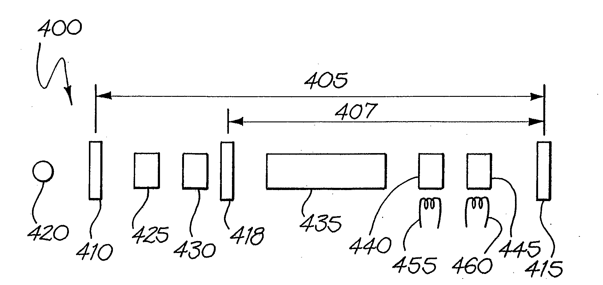
[0222]FIG. 6 shows an experimental setup for a selectable laser system 600 according to the present invention. In FIG. 6, a bent cavity 610 is defined by a reflective face 615 on a laser material 635 and reflectors 620 and 625. The reflective face 615 is transmissive at 808 nm, and reflective at all cavity wavelengths (ie 532 nm, 555 nm, 579 nm, 1064 nm and 1158 nm). The reflector 625 is a 20 cm radius of curvature dielectric mirror which is reflective at all cavity wavelengths, and the reflector 620 is a flat dichroic mirror which is transmissive at the visible wavelengths of 532 nm (green), 555 nm (lime) and 579 nm (yellow), and reflective at other cavity wavelengths (1064 nm and 1158 nm). With the exception of the reflective face 615, all faces of components 635, 640, 645 and 650 are antireflection coated at 1064 nm and at 1158 nm. Arrow 630 represents a pump beam with a wavelength of 808 nm, which can cast a 0.2 mm spot on the laser material 635 with power of about 22 W. The las...

example 3

[0240]A Raman laser, comprising a fibre-coupled diode, Nd:YAG laser crystal and KGd(WO4)2 crystal, and in addition an AO Q-switch and non-linear crystal, was constructed to demonstrate wavelength selectability. Wavelength selectability has been demonstrated using angle-tuning of LBO, angle-tuning of BBO, and temperature tuning of LBO. For temperature tuning LBO, two crystals, LBO1 (=0, =0) and LBO2 (=0, =5), were used because the range of temperatures required for a single LBO crystal was too high. The key results are summarised below.

TABLE CPhase-matching532 nm555 nm579 nm606 nm636 nmLBO angle-tune1.7 W0.95 W1.8 W——LBO temp-tune1.5 W0.52 W0.57 W  0.2 W—BBO angle-tune1.3 W0.45 W1.0 W0.25 W0.04 W

[0241]The highest output powers were obtained by angle tuning of LBO, however the relatively large tuning range limited the number of output wavelengths. Temperature tuning of LBO has an advantage that cavity mirror re-alignment is not required and wavelength selection is easily controlled el...


PUM


Abstract

The invention provides a laser system (100) wherein the output may be selected from two or more different wavelengths of output laser light. The system (100) comprises a laser capable of having at least two different wavelengths of laser light resonating in the cavity (105) simultaneously. One of the frequencies is generated by a Raman crystal (135) which shifts the frequency of light generated by the lasing medium (125). A tunable non-linear medium (140), such as LBO, is provided in the cavity for selectively frequency converting at least one of the at least two different wavelengths of laser light. The conversion may be SHG, SFG or DFG for example. A tuner (145) is provided to tune the non-linear medium to select the particular wavelength to convert. Temperature tuning or angle tuning of the non-linear medium can be used. A Q switch (130) may also be provided in the cavity. The output laser beam can be used for treatment, detection or diagnosis of a selected area on or in a subject, and can be used in opthalmological and dermatological fields.

Description

TECHNICAL FIELD[0001]The present invention relates to a selectable multiwavelength laser system, a method for selectably providing an output laser beam from a laser system at different wavelengths and methods of using laser light.BACKGROUND OF THE INVENTION[0002]Solid-state Raman lasers are a practical and efficient approach to optical frequency down conversion, offering high (up to 70 to 80%) conversion efficiencies with respect to the pump power, excellent beam quality and ease of alignment. In recent years use of crystals for stimulated Raman scattering (SRS) has been gaining interest because, in comparison with high-pressure gaseous and dye (liquid) Raman lasers, crystalline Raman lasers offer better gain, better thermal and mechanical properties, and the ability to operate at high pulse repetition frequency. Further they are compatible with compact all solid-state laser technology.[0003]Solid-state lasers are commonly used in the opthalmological and dermatological fields. For t...

Claims


Application Information

Patent Timeline
Patent Type & Authority Applications(United States)
IPC IPC(8): H01S3/30H01S3/10H01S3/08
CPCH01S3/08086H01S3/11H01S3/1086H01S3/109H01S3/1123H01S3/1611H01S3/1643
Inventor PIPER, JAMES AUSTINPASK, HELEN MARGARETOGILVY, HAMISHMILDREN, RICHARD PAUL
Owner MACQUARIE UNIV
Why Eureka
Try Eureka