
Water electrolysis system

a water electrolysis system and electrolysis technology, applied in the direction of electrode coatings, cell components, multiple component coatings, etc., can solve the problems of reducing the current efficiency of gas production, deteriorating the performance of the water electrolysis system in terms of purity, and extremely thin electrode catalyst layer

Inactive Publication Date: 2008-10-30
CHLORINE ENGINEERS CORP LTD
View PDF19 Cites 35 Cited by
  • Summary
  • Abstract
  • Description
  • Claims
  • Application Information

AI Technical Summary

Benefits of technology

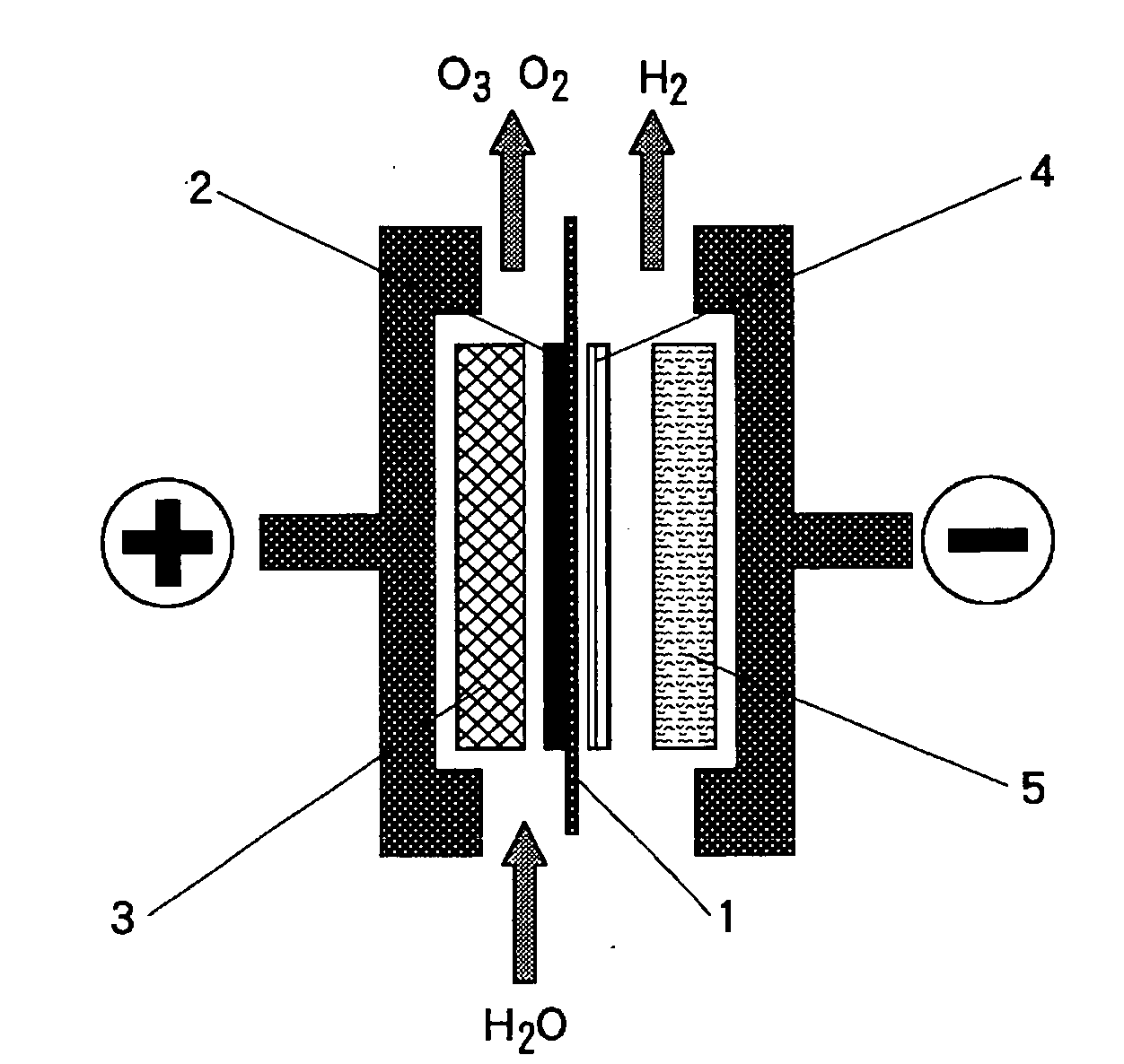
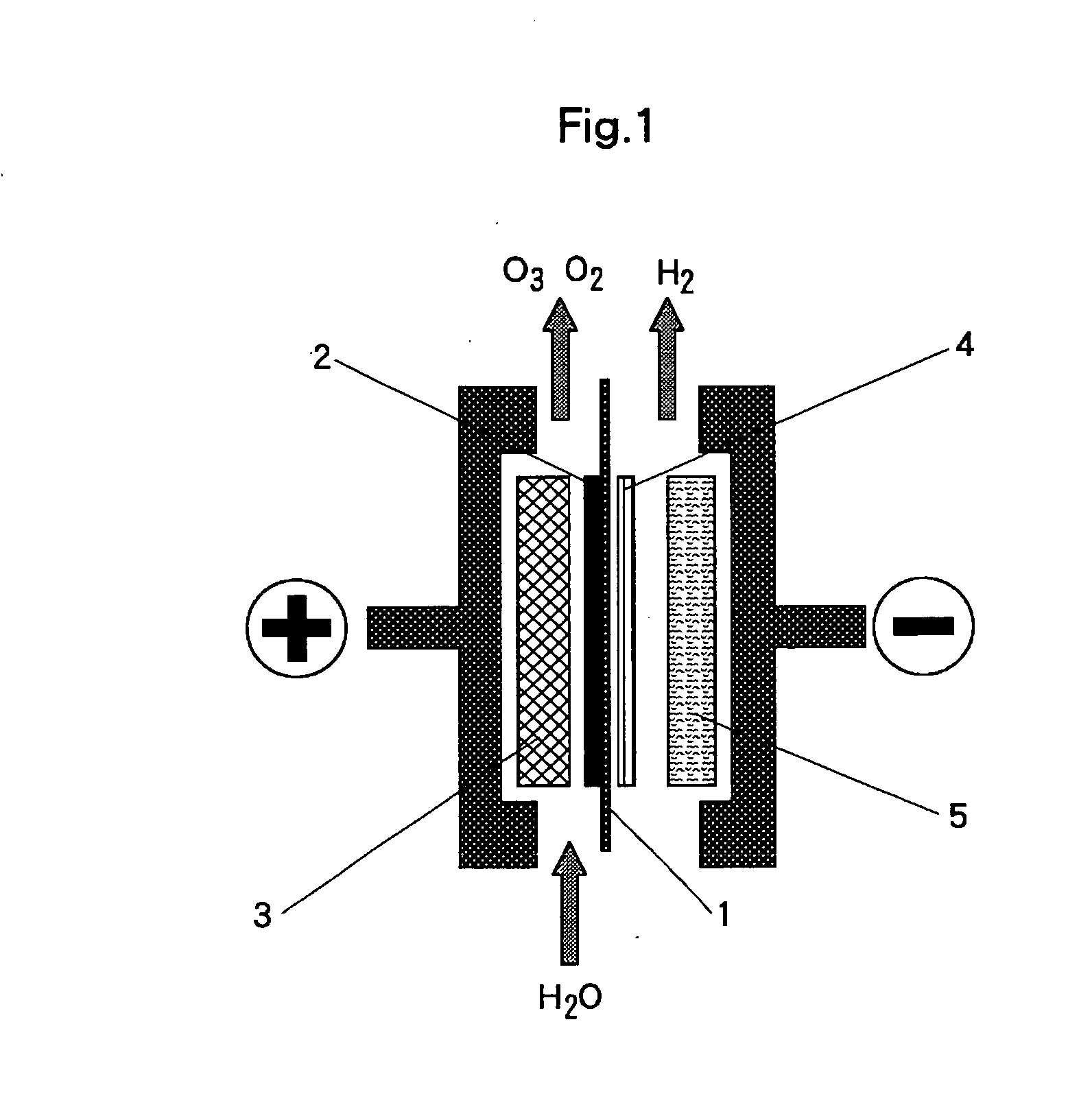
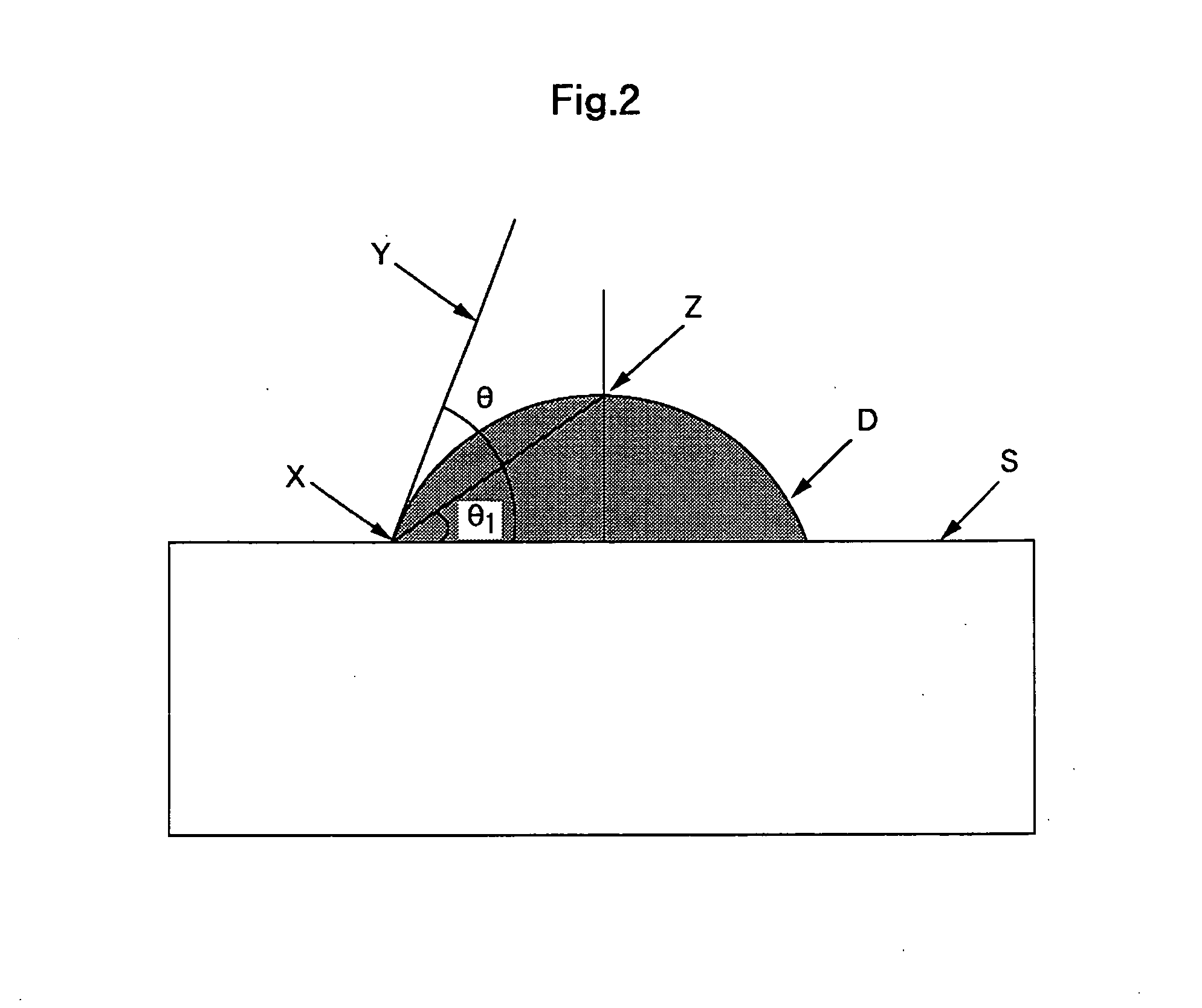
"The present invention has developed a water electrolysis system that uses a solid polymer electrolyte membrane with a porous structure containing anode or cathode catalyst, which is tightly attached to the membrane. The surface of the membrane is hydrophobized, with a water contact angle of 90 degrees or more. The use of fluorine resin containing resin as the material for the porous structure is effective in solving problems associated with the water electrolysis system. The various methods for applying the porous structure to the anode or cathode catalyst layer are described, including the use of platinum or platinum-loaded carbon grains, a porous metal plate or sintered sheet of metallic fiber, or a fluorine resin layer coated on the surface of the cathode catalyst layer. These methods improve the efficiency and performance of the water electrolysis system."

Problems solved by technology

(Refer to JP 6-41639) The cation exchange membrane / electrode catalyst structure prepared by this method shows satisfactory contact between the cation exchange membrane and electrode catalyst, but has such problems that the electrode catalyst layer is extremely thin; the electrode catalyst tends to have the concentration distribution of electrode catalyst in the direction of the cation exchange membrane thickness depending on the adsorption conditions such as concentration or temperature of metal salt solution; uniform contact with the current collector is difficult because formed electrode catalyst layer is thin; applicable electrode catalyst is limited to metals that are formable by using reducing agent.
Gas transfer to the counter electrode leads to performance deterioration of the water electrolysis system in terms of decrease in purity of the gas produced as the counter electrode gas and decrease in current efficiency of gas production.

Method used


Image

  • Water electrolysis system
  • Water electrolysis system
  • Water electrolysis system

Examples


example 1

[0042]A sintered sheet of titanium fiber (manufactured by Tokyo Rope Mfg. Co., Ltd.), 1 mm thick, was washed with neutral detergent for degreasing and subject to pretreatment by acid pickling with 20 wt % hydrochloric acid solution for one minute at 50 degrees Celsius; then, on the said sintered sheet of titanium fiber, a coating comprising platinum-titanium-tantalum (25-60-15 mol %) was formed by the thermal decomposition method; and thus the anode current collector or the anode substrate with an underlayer on the surface is prepared.

[0043]Using said anode current collector or anode substrate as the anode, and 400 g / l of lead nitrate solution as electrolyte, electrolysis was performed for 60 minutes at 60 degrees Celsius at the current density of 1 A / dm2 to form a coating layer of β—lead dioxide, which is anode catalyst, on the anode current collector or the anode substrate surface.

[0044]A commercially available perfluorosulfonic acid type cation exchange membrane (Registered Trade...

example 2

[0049]Cathode Sheet B was prepared in such way that an aqueous dispersion of PTFE dispersion and platinum-loaded carbon catalyst was applied with a brush on carbon paper (100 μm thick) surface, followed by drying, and this process was repeated three times to form Cathode Sheet B in porous structure comprising a carbon paper substrate of 110 μm thick. The contact angle with the catalyst coating surface of Cathode Sheet B was 95 degrees.

[0050]The electrolysis test was conducted as in Example 1, the results of which illustrated the concentration of ozone in the anode gas: 11.4 Vol. %, concentration of hydrogen gas in the anode gas: 0.10 Vol. %, and the cell voltage: 3.3 v.

example 3

[0051]A sintered sheet of titanium fiber, 1 mm thick, was washed with neutral detergent for degreasing and subject to pretreatment by acid pickling with 20 wt % hydrochloric acid solution for one minute at 50 degrees Celsius; then, on the said sintered sheet of titanium fiber, iridium dispersion prepared by dispersing iridium powder (under 200 mesh) in PTFE dispersion was applied with a brush until the final coating amount reached 250 g / m2 as iridium, followed by drying and thus, an iridium coated anode with a sintered sheet of titanium fiber was obtained.

[0052]The electrolysis test was conducted as in Example 1, wherein oxygen generated at the anode and hydrogen generated at the cathode and the results of which illustrated the concentration of hydrogen gas in the anode gas: 0.07 Vol. %, and the cell voltage: 2.5 v. For the cathode, Cathode Sheet A in porous structure was used, wherein the contact angle with the catalyst coating surface was 95 degrees


PUM

PropertyMeasurementUnit
water contact angleaaaaaaaaaa
contact angleaaaaaaaaaa
thickaaaaaaaaaa

Abstract

In a water electrolysis system having an anode catalyst layer containing anode catalyst and a cathode catalyst layer containing cathode catalyst tightly attached, respectively, to each surface of a solid polymer electrolyte membrane comprising a cation exchange membrane, wherein at least one catalyst layer of said anode catalyst layer and cathode catalyst layer comprises a porous structure of anode catalyst or cathode catalyst dispersed in fluorine resin containing resin, featuring the surface of the anode catalyst layer or the cathode catalyst layer being hydrophobized and the water contact angle with the surface of the anode catalyst layer or the cathode catalyst layer of said porous structure being 90 degrees or more, whereby the transfer of gas to the counter electrode can be significantly suppressed, gas purity and current efficiency be improved, and safety operation of the electrolysis system be secured, without a major change in configuration of the water electrolysis system.

Description

BACKGROUND OF THE INVENTION[0001]1. Field of the Invention[0002]This invention relates to a water electrolysis system for generating oxygen and hydrogen or for generating ozone by water electrolysis in which an anode and a cathode are tightly attached, respectively, to each surface of a solid polymer electrolyte membrane comprising a cation exchange membrane, enabling hydrogen gas or oxygen gas generated at the cathode or the anode to be suppressed against transferring to the counter electrode through the cation exchange membrane, the purity of the gases to be enhanced, and safe electrolysis operation to be secured for a long time.[0003]2. Description of the Related Art[0004]An electrolysis system which is composed by attaching an anode and a cathode to each surface of a solid polymer electrolyte membrane comprising a cation exchange membrane has been widely used as a superior energy-effective electrolysis system for its advantages including a low electrolytic voltage, availability ...

Claims


Application Information

Patent Timeline
Patent Type & Authority Applications(United States)
IPC IPC(8): C25B9/10C25B9/23
CPCC25B1/04C25B11/035C25B11/0489H01M4/8605H01M4/90H01M4/926Y02E60/366Y02E60/50Y02E60/36C25B11/095C25B11/031C25B9/23
Inventor KATO, MASAAKIOGAWA, YUSUKE
Owner CHLORINE ENGINEERS CORP LTD
Learn More