Plasma display panel and its production process

a technology of plasma and display panel, which is applied in the manufacture of electrode systems, cold cathode manufacturing, electric discharge tube/lamp manufacture, etc., can solve the problems of difficult to obtain a pdp having favorable properties and insufficient secondary electron discharge of films, and achieve favorable discharge properties, high ultraviolet luminous efficiency, and high discharge efficiency

Inactive Publication Date: 2008-10-30
ASAHI GLASS CO LTD
View PDF5 Cites 16 Cited by
  • Summary
  • Abstract
  • Description
  • Claims
  • Application Information

AI Technical Summary

Benefits of technology

[0021]The PDP comprising a protective layer containing a Mayenite compound of the present invention has favorable discharge properties such as a high ultraviolet luminous efficiency, a high discharge efficiency and a short discharge delay, and is chemically stable.

Problems solved by technology

The problem here is that the MgO film discharges no sufficient secondary electrons for plasma formation by the entrance of Xe ions, whereby it discharges sufficient secondary electrons by entrance of Ne ions (Non-Patent Document 1).
Further, MgO is a chemically unstable substance in the air, and accordingly it is difficult to obtain a PDP having favorable properties unless an activating treatment of carrying out heat treatment in vacuum is carried out.

Method used


Image

  • Plasma display panel and its production process
  • Plasma display panel and its production process
  • Plasma display panel and its production process

Examples


example 1

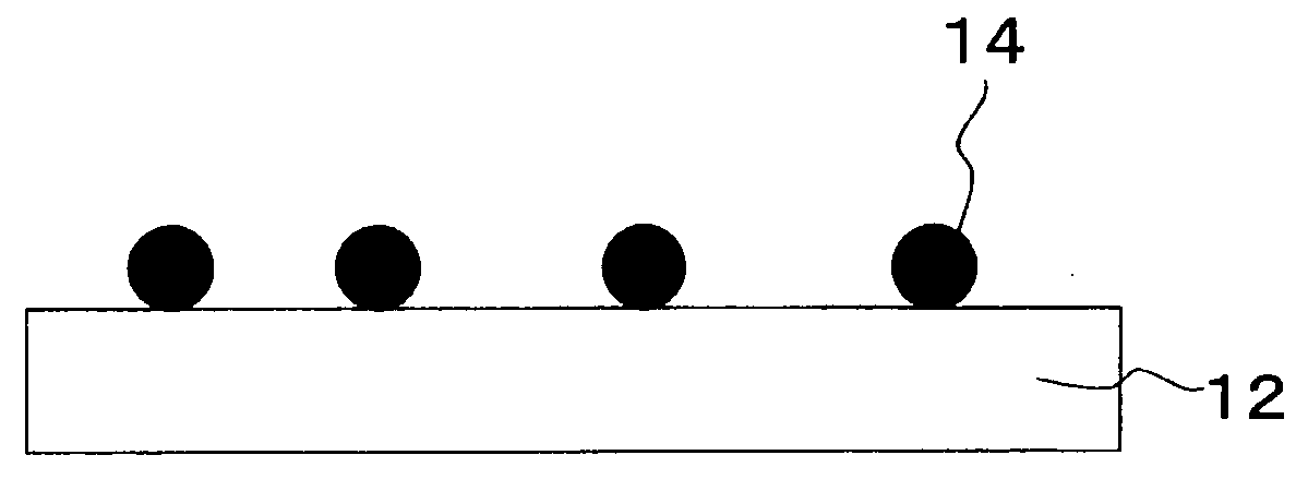
[0083]Calcium carbonate and aluminum oxide were mixed in a molar ratio of 12:7 and held in the air at 1,300° C. for 6 hours to prepare a 12CaO.7Al2O3 compound (hereinafter referred to as a C12A7 compound). The powder was formed into a molded product by a uniaxial pressing machine, and the molded product was held in the air at 1,350° C. for 3 hours to prepare a sintered product having a sintered density exceeding 99%. This sintered product was a white insulant showing no electrical conductivity (hereinafter referred to as sample B).

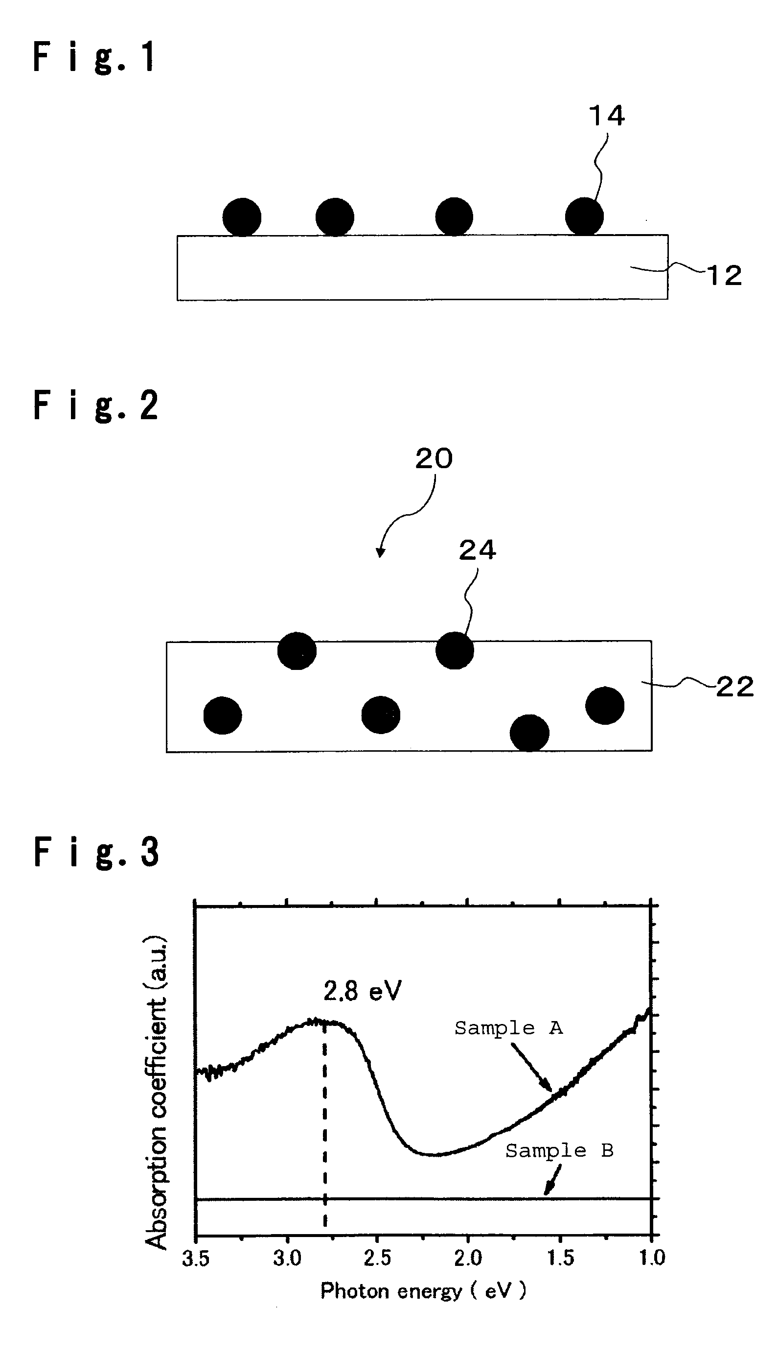
[0084]The sintered product together with metal aluminum was put in an alumina container with a lid and heated to 1,300° C. in a vacuum furnace and held for 10 hours and then slowly cooled to room temperature. The obtained heat treated product was black brown and confirmed to have a peak of a Mayenite structure as measured by X-ray diffraction. Further, it was found from a light absorption spectrum as measured by U3500 manufactured by Hitachi, Ltd. that it ...

example 2

[0087]A bulk prepared in the same manner as in preparation of sample A in Example 1, was crushed in a mortar to prepare a powder (hereinafter referred to as powder A). The particle size distribution of powder A was measured by means of laser diffraction scattering method using SALD2100 manufactured by Shimadzu Corporation and as a result, the average particle size was 5 μm. Powder A was supported on an electrically conductive tape, and measurement was carried out in the same manner as in Example 1 without carrying out annealing treatment and as a result, the secondary emission coefficient γ was 0.22.

example 3

[0088]Calcium carbonate and aluminum oxide were mixed in a molar ratio of 12:7 and held in the air at 1,300° C. for 6 hours to prepare a C12A7 compound. The powder was formed into a molded product by a uniaxial pressing machine, and the molded product was held in the air at 1,350° C. for 3 hours to prepare a sintered product having a sintered density exceeding 99%. The sintered product was a white insulant showing no electrical conductivity. The sintered product was put in a carbon crucible with a lid, put in a tubular furnace through which nitrogen flowed, held at 1,300° C. for 3 hours and then cooled to room temperature. The obtained compound was green. The compound was subjected to measurement of X-ray diffraction, a light scattering reflection spectrum and ESR and confirmed to be an electrically conductive C12A7 compound having an electron concentration of about 1020 / cm3 (hereinafter referred to as sample C).

[0089]With respect to sample C, secondary emission properties were meas...


PUM


Abstract

For a PDP, a panel having favorable discharge properties such a high discharge efficiency and a short discharge delay, being chemically stable and capable of electric power saving, is desired.
A plasma display panel comprising a front substrate and a rear substrate facing each other via a discharge space, discharge electrodes formed on at least one of the front substrate and the rear substrate, a dielectric layer covering the discharge electrodes, and a protective layer covering the dielectric layer, wherein the protective layer contains a Mayenite compound, and the secondary emission coefficients when Ne and Xe are used as excited ions at an accelerating voltage of 600 V, are respectively at least 0.05 at a secondary electron collector voltage at which secondary electrons can be sufficiently captured.

Description

TECHNICAL FIELD[0001]The present invention relates to a plasma display panel.BACKGROUND ART[0002]A plasma display panel (hereinafter referred to as PDP) has such a structure that one of two glass substrates facing each other with a discharge space in which a discharge gas is sealed, has pairs of display electrodes extending in the lateral direction arranged in the lengthwise direction, and the other has sustaining electrodes extending in the lengthwise direction arranged in the lateral direction, and at intersections of the pairs of display electrodes and the sustaining electrodes in the discharge space, matrix unit luminescence regions (discharge cells) are formed.[0003]The operation principle of a PDP is to utilize a luminescence phenomenon accompanying the gas discharge. As its structure, it has barrier ribs between a transparent front substrate and a back substrate facing each other, and cells (space) are partitioned by the barrier ribs. Into the cells, a Penning gas mixture suc...

Claims


Application Information

Patent Timeline
Patent Type & Authority Applications(United States)
IPC IPC(8): H01J17/49H01J9/02
CPCH01J9/02H01J11/12H01J11/40H01J11/38H01J11/50
Inventor WEBSTER, SATORUITO, SETSURO
Owner ASAHI GLASS CO LTD
Why Eureka
Try Eureka