Method of Forming a Flexible Heating Element

a heating element and flexible technology, applied in the field of heating element formation, can solve the problems of difficult to meet the needs difficult to meet the requirements of high current throughput applications, and the wires used in such circuits are particularly fragile, and achieve economic production, effective transparency, and simple application

Inactive Publication Date: 2008-11-27
EASTMAN KODAK CO
View PDF10 Cites 11 Cited by
  • Summary
  • Abstract
  • Description
  • Claims
  • Application Information

AI Technical Summary

Benefits of technology

[0018]The heating element according to the present invention is more economical to produce than the known prior art. It is more effectively transparent than known prior art offering evenly-distributed heating. It is also sufficiently robust for the desired purposes and is not limited to being embedded in the windscreen. It may be a replaceable, separately mounted layer on the inner or outer surface of the windscreen or visor material for which it is intended to provide the heating effect.
[0019]Furthermore, the heating element according to the present invention may be produced on a separate transparent flexible support to the substrate to be heated and then subsequently laminated to the substrate to be heated, e.g. a windscreen. The method of the present invention provides a more economical method of producing suitable heating elements than the known prior art methods of providing evenly distributed heating.
[0020]The heating element of the present invention may be formed on a flexible support, enabling simple application to curved surfaces to be heated and ease of handling. It is furthermore capable of delivering a power dissipation of 5 W / d2 without degradation and distortion of the materials. It is also capable of being lightweight, thereby leading to low installation and delivery costs. Fabrication of the heating elements according to the present invention also has the advantage of being a relatively simple process and of relatively low cost.

Problems solved by technology

Difficulties with this method include the unsuitability for high current throughput applications and complex production of the tape.
The wires used in such circuitry are particularly fragile as they have to be sufficiently thin to enable the substrate to remain effectively transparent to the user.

Method used


Image

  • Method of Forming a Flexible Heating Element
  • Method of Forming a Flexible Heating Element
  • Method of Forming a Flexible Heating Element

Examples


example 1

[0119]A photosensitive film was prepared which on the backside contained an antihalation layer with protective topcoat and on the front side an emulsion layer sensitive to red light, with a protective topcoat.

The Antihalation Layer:

[0120]A dispersion was prepared by the addition of 13.3 kg water to 705 g lime processed ossein (LPO) gelatin. After soaking, the gelatin was dissolved at 49° C. and the pH was adjusted using dilute sulfuric acid to 5.3. 239 g 2-(3-acetyl-4-(5-(3-acetyl-1-(2,5-disulfophenyl)-1,5-dihydro-5-oxo-4H-pyrazol-4-ylidene)-1,3-pentadienyl)-5-hydroxy-1H-pyrazol-1-yl)-1,4-benzenedisulfonic acid, pentasodium salt [CAS No 127093-24-7] as a 10% aqueous dispersion was added, followed by 188 g 4-(4,5-dihydro-4-(5-(5-hydroxy-3-methyl-1-(4-sulfophenyl)-1H-pyrazol-4-yl)-2,4-pentadienylidene)-3-methyl-5-oxo-11H-pyrazol-1-yl)-benzenesulfonic acid [CAS No 27969-56-8] as a 13% aqueous dispersion, followed by 1.1 kg Ludox™ AM, a 30% silica dispersion available from W. R. Grace, ...

example 2

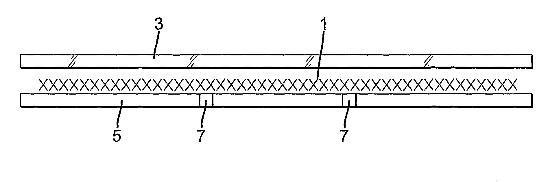
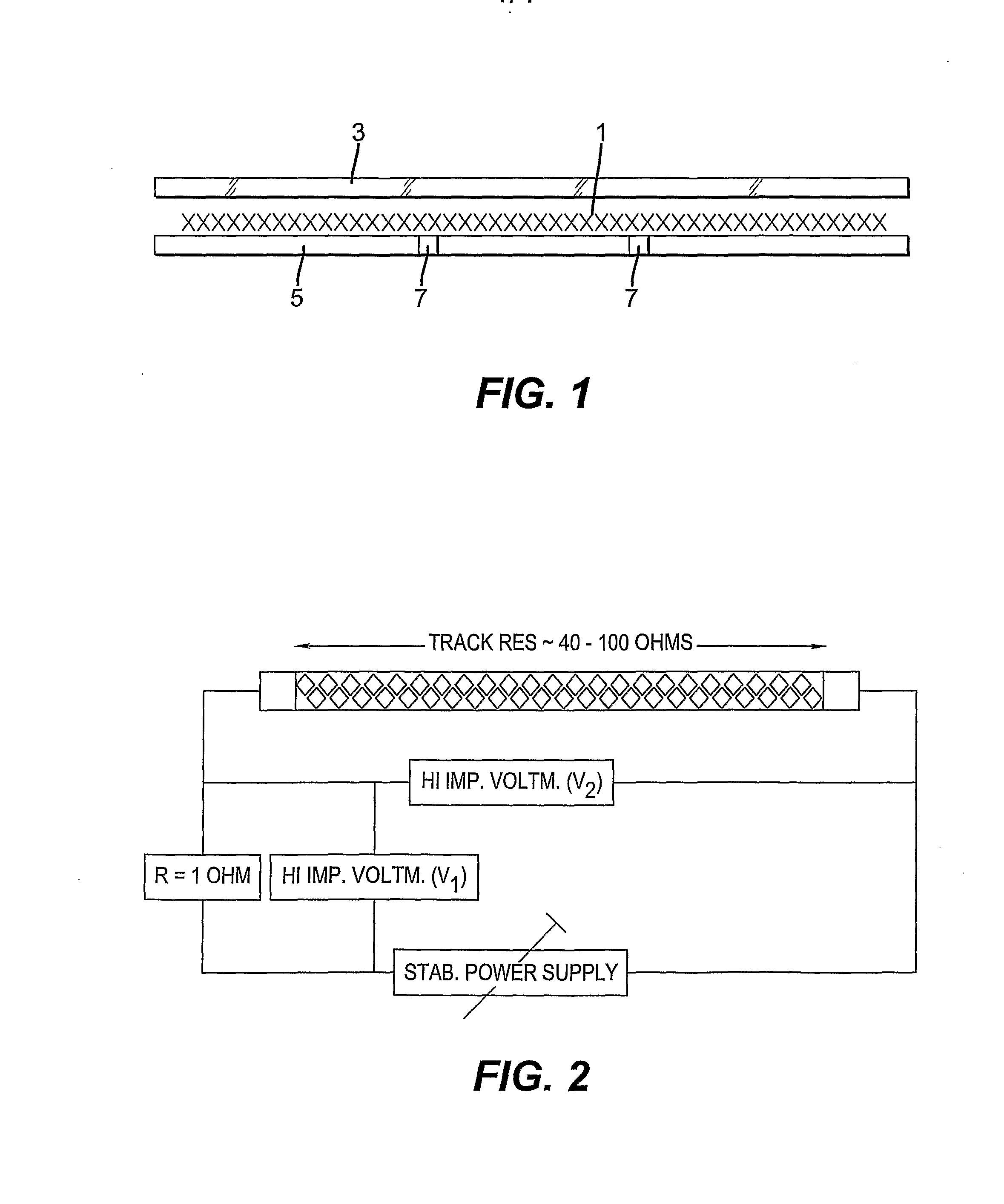
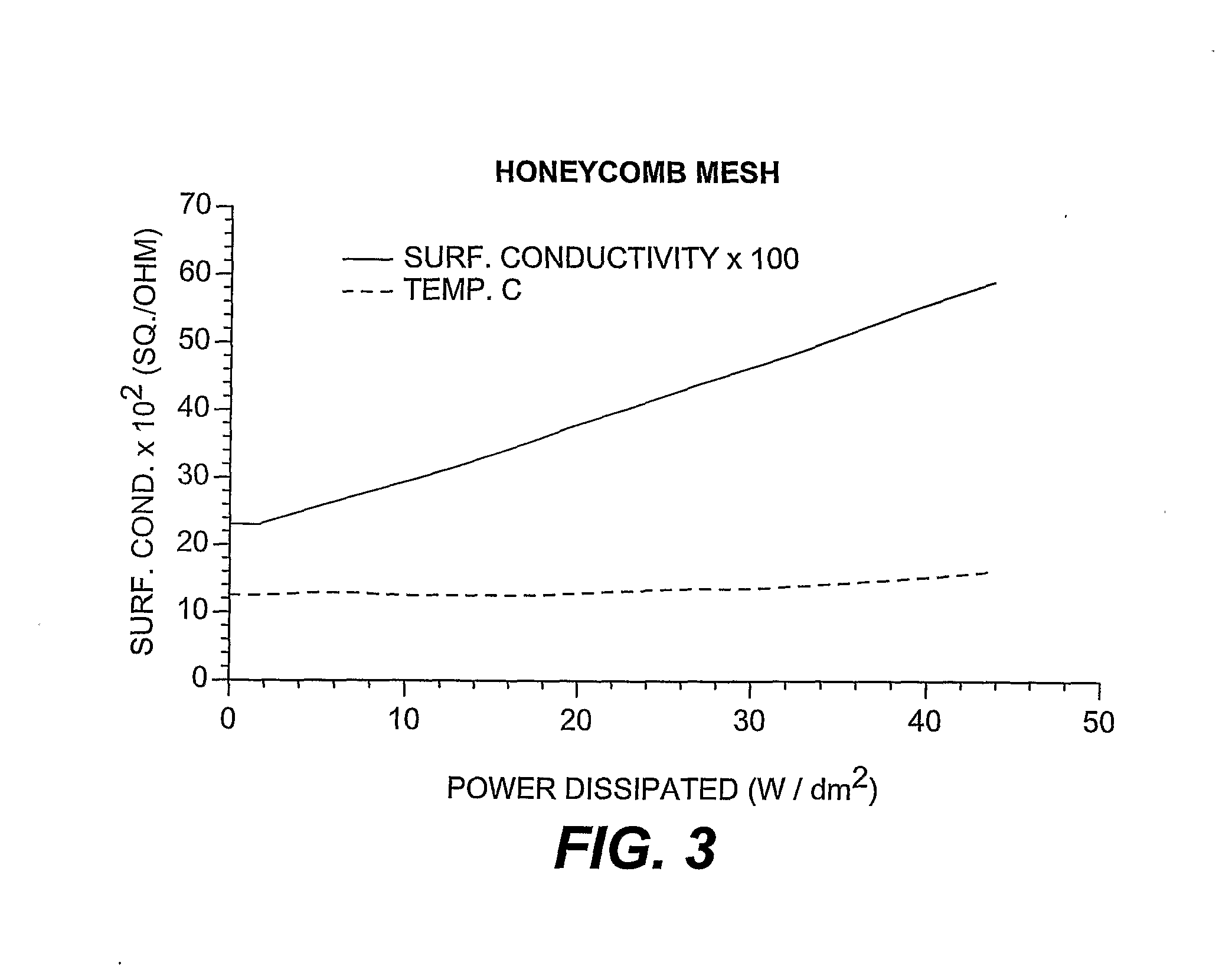
[0135]In this example, the sample was a honeycomb mesh of 6.8 cm×0.5 cm, formed by the method of Example 1. A surround area on each side to a depth of 0.15 cm made the total area 6.4 cm2. The overall sheet resistivity of this sample was measured at 7.83 ohms / square and the mesh area had an optical transmission of 92%, including the base and background photographic fog. As shown in FIG. 1, the mesh on its support (1) was clamped between a microscope slide (3) (in contact with the mesh side) and an aluminium base (5) containing two temperature sensors (7) (in contact with the bare support). One or two drops of silicone oil were used to provide good thermal contact between the flexible support and the glass and aluminium surfaces.

[0136]A circuit, as shown in FIG. 2, was used to monitor the performance of the mesh as a heating element, by determination of the temperature and conductivity profiles and the breakdown power.

[0137]For car windscreen applications it is well known that heat di...

example 3

[0138]Two meshes were produced by the method of Example 1 with nominal 10 μm lines spaced 250 μm apart. Both were grown for the same length of time (1 h) in a plating bath but Sample 1 was ultrasonically treated. The mesh of Sample 1 (see FIG. 4) had a sheet resistance of 5.5 Ω / square. The tracks had a sheet resistance of 0.14 Ω / square and the transparency of the mesh was >85%.

[0139]Sample 2 was processed in the same way, held vertically in the container but without any ultrasonic agitation. The mesh of Sample 2 (see FIG. 5) consisted of tracks with a sheet resistance of 0.19 Ω / square, with the mesh itself having a sheet resistance of 5.5 Ω / square. The transmission of this mesh was <70%.

[0140]As can be seen from FIGS. 4 and 5, the ultrasonic agitation had inhibited the adherence of unwanted silver nodules, either to the sides of the wire or in the background area.


PUM

PropertyMeasurementUnit
widthaaaaaaaaaa
diameteraaaaaaaaaa
sheet resistanceaaaaaaaaaa

Abstract

The present invention provides a method of manufacturing a heating element having a desired pattern of conductive tracks forming a power dissipative conductive track pattern with a desired resistivity and power output, the method comprising providing a photosensitive or pressure-sensitive element comprising: a support having coated on at least one side thereof a photo-sensitive or pressure-sensitive layer, which is capable of, upon imagewise radiation or pressure exposure according to the desired pattern and development of the resulting latent image, providing a metal image according to the desired pattern; imagewise radiative- or pressure-exposing the layer of the element according to a desired conductive pattern to form a latent image in the layer; and developing the element to form a conductive metal pattern, corresponding to the pattern of the latent image, on the support. The heating element may be formed on a flexible support and finds particular utility in heated window/windscreen applications.

Description

FIELD OF THE INVENTION[0001]The present invention relates to the formation of heating elements on flexible supports for the purpose of providing heat to windows, windscreens etc. in order to reduce condensation or frost formed thereon and to improve transparency. The invention is particularly concerned with the formation of resistive metal tracks according to a desired pattern, whereby connection of each end of the track pattern to an appropriate power source enables the track pattern to provide a suitable and desirable heating effect to a substrate to which the track pattern is physically applied. The invention finds particular utility in heated window / windscreen applications.BACKGROUND OF THE INVENTION[0002]Vehicles, e.g. automotive vehicles, railway locomotives, water-going crafts and aircrafts, require clear vision for their operators in all weathers. Personal outdoor equipment incorporating visors in some form have similar requirements. Certain items of optical equipment, e.g. ...

Claims


Application Information

Patent Timeline
Patent Type & Authority Applications(United States)
IPC IPC(8): H05B3/06G03F7/20B32B17/10G03C5/58H05B3/84
CPCB32B17/10036B32B17/10174B32B17/10376G03C5/58H05B2203/014G03C1/85G03C2007/3025
Inventor WINSCOM, CHRISTOPHER J.FYSON, JOHN R.HEWITSON, PETERRIDER, CHRISTOPHER B.SLATER, SEAN D.
Owner EASTMAN KODAK CO
Why Eureka
Try Eureka