

IrOx nanowire neural sensor
a neural sensor and nanowire technology, applied in the field of integrated circuit fabrication, can solve the problems of easy damage to the retina, limited surface area of the maximum charge an electrode can deliver, and tissue resistance to electrical stimulation is very high, so as to improve the surface to volume ratio, improve the resolution of the making, and stimulate the effect of targeted areas
- Summary
- Abstract
- Description
- Claims
- Application Information
AI Technical Summary
Benefits of technology
Problems solved by technology
Method used
Image

Examples
Embodiment Construction
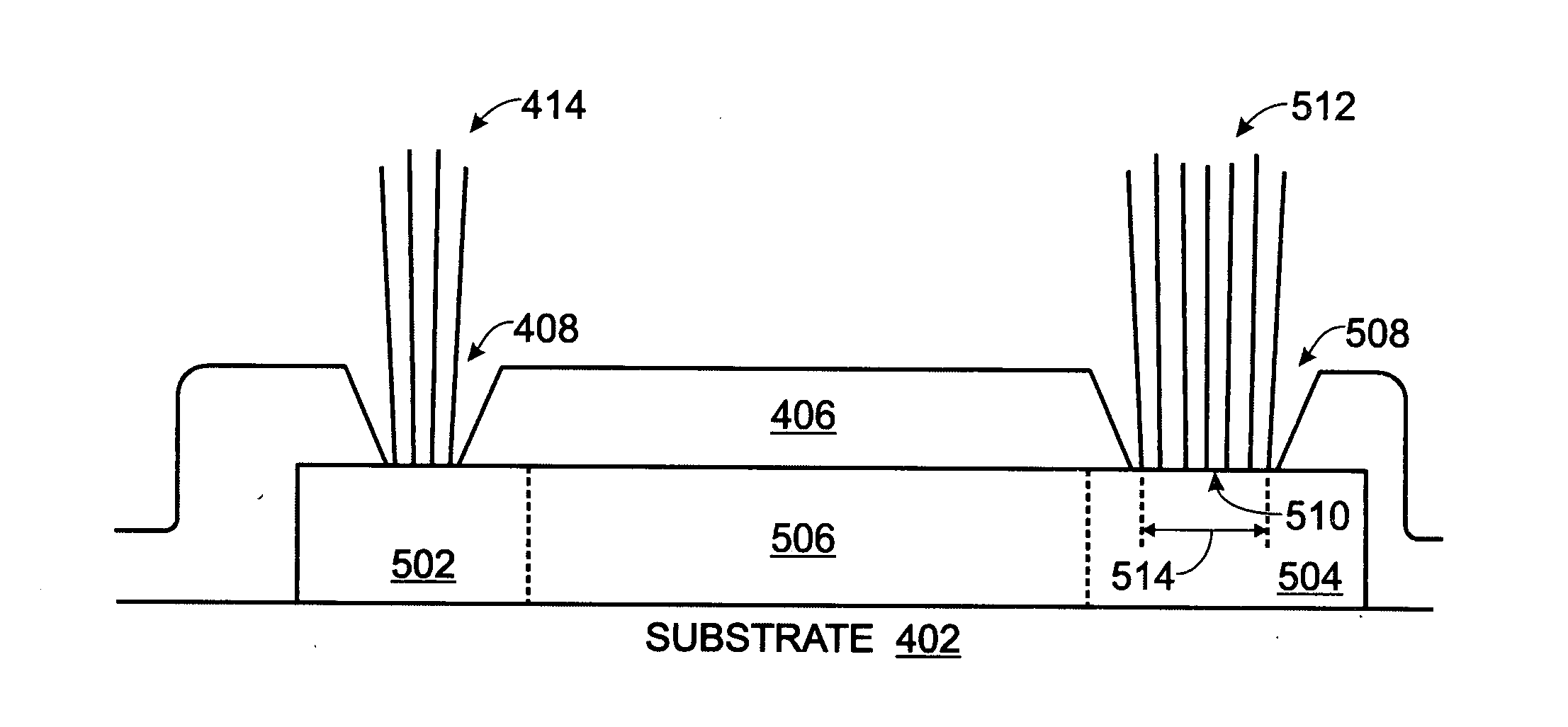
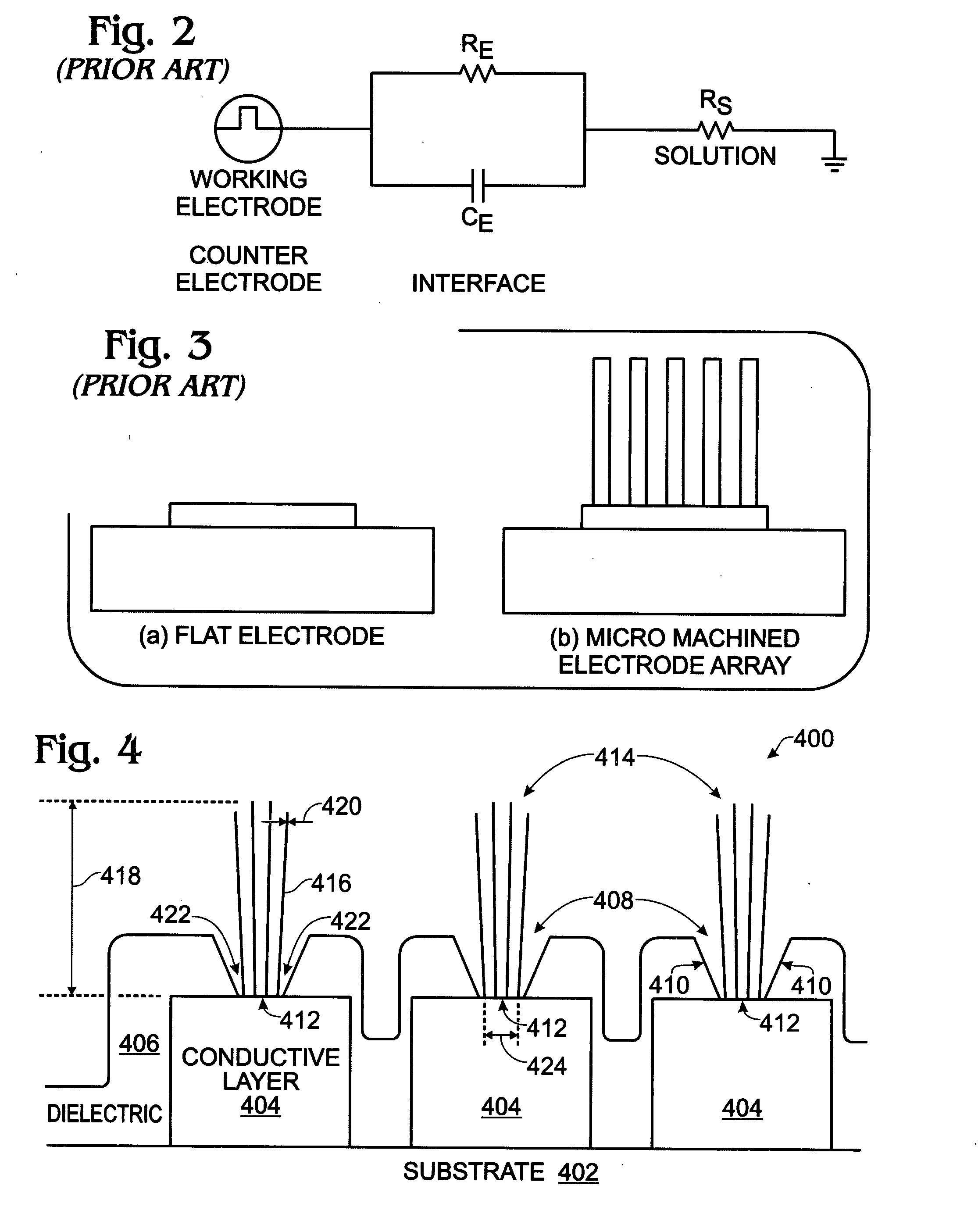
[0031]FIG. 4 is a partial cross-sectional view of an iridium oxide (IrOx) nanowire neural sensor array. The array 400 comprises a substrate 402 and a conductive layer 404 overlying the substrate 402. A dielectric layer 406 overlies the conductive layer 404. Contact holes 408 with sloped walls 410 are formed in the dielectric layer 406, exposing regions 412 of the conductive layer 404. IrOx nanowire neural interfaces 414 are shown, grown from the exposed regions 412 of the conductive layer 404. With respect to IrOx, typically x is ≦4. Although only 3 interfaces 414 are shown, the array is not limited to any particular number of interfaces. A nanowire may alternately be known as a nanostructure, nanorod, nanotip, or nanotube.
[0032]The average IrOx nanowire 416 has an aspect ratio in a range of about 1:1 to about 1:1000. As used herein, aspect ratio is defined as the ratio of the nanowire height 418, to the nanowire diameter or width 420 at proximal end 422 (base) attached to the condu...
PUM
| Property | Measurement | Unit |
|---|---|---|
| area | aaaaa | aaaaa |
| diameter | aaaaa | aaaaa |
| charge | aaaaa | aaaaa |
Abstract
Description
Claims
Application Information