Method and process for deposition of textured zinc oxide thin films

a technology of textured zinc oxide and thin film, which is applied in the direction of vacuum evaporation coating, coating, semiconductor devices, etc., can solve the problems of unstable material, low cost of photovoltaic production industry, and darkening of tin oxide tco, and achieves low cost and large coating width

Inactive Publication Date: 2008-12-18
NEW MILLENNIUM SOLAR EQUIP CORP
View PDF7 Cites 39 Cited by
  • Summary
  • Abstract
  • Description
  • Claims
  • Application Information

AI Technical Summary

Benefits of technology

[0009]The present invention solves one or more problems of the prior art, by providing in at least one embodiment a method for sputtering a textured zinc oxide coating onto a substrate by reactive-environment hollow cathode sputtering. The method of this embodiment comprises providing a sputter reactor that has a cathode channel and a flow exit end. The cathode channel allows a gas stream to flow therein and exit from the flow exit end. This cathode channel is at least partially defined by a channel defining surface that includes at least one zinc containing target and an optional dopant target. The dopant target when present is positioned to provide dopant atoms to the gas stream when the gas stream is flowed through the cathode channel. A gas is flowed through the channel, such that the gas emerges from the flow exit. A plasma is then generated such that material is sputtered off the channel-defining surface and the dopant target to form a gaseous mixture containing zinc atoms and dopant atoms (if present) that are transport...

Problems solved by technology

However, the former material is unstable and the latter involves an undesirable wet chemical step involving acid.
SnO2 is susceptible to reduction when exposed to atomic hydrogen d...

Method used


Image

  • Method and process for deposition of textured zinc oxide thin films
  • Method and process for deposition of textured zinc oxide thin films
  • Method and process for deposition of textured zinc oxide thin films

Examples


example # 1

Example #1

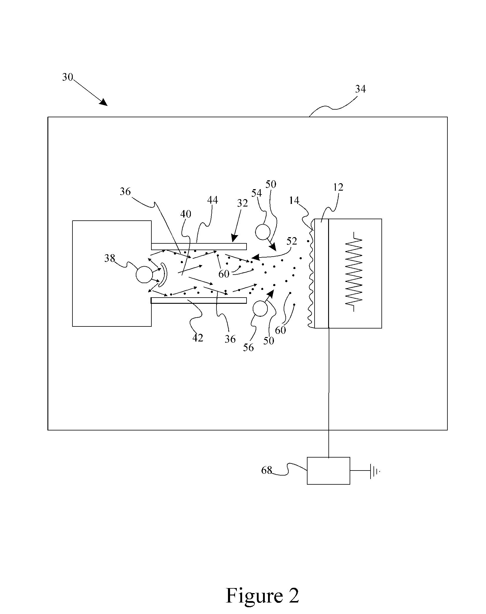
[0054]An RE-HCS deposition system containing a linear hollow cathode was fitted with two facing Zn targets 11.4 cm in length and 3.8 cm in breadth. The width of the exit slot so defined was 1.25 cm. An Ar flow of 2 slm was used as the working gas. The reactive gas was water carried by about 100 sccm Ar from a bubbler. The doping element is supplied by sputtering a separate Al bar. Mid-frequency pulsed (bipolar) power was applied on Zn target and Al bar at 100 kHz at a level of 300 W and 100 W, respectively. The chamber pressure was 170 mTorr. The substrate temperature was 230° C. The substrate bias is −80V by RF power. A 1.7 μm ZnO:Al film was grown in 30 minutes using 22 passes across the cathode. The sheet resistance was 4.12 ohm / square corresponding to a film resistivity of 7.0×10⁻⁴ ohm-cm. The film was found to be strongly textured as shown in the scanning electron micrograph of FIG. 3. Further analysis by atomic force microscopy revealed the RMS surface roughness to b...

example # 2

Example #2

[0055]The deposition set-up is similar to example #1. An Ar flow of 2 slm was used as the working gas. The reactive gas was water vapor supplied without an Ar carrying gas. Mid-frequency pulsed (bipolar) power was applied on Zn target and Al bar at 100 kHz at a level of 300 W and 100 W, respectively. The chamber pressure was 170 mTorr. The substrate temperature was 240° C. A 0.99 μm ZnO:Al film was grown in 18 minutes using 13 passes across the cathode. The sheet resistance was 8 ohm / square corresponding to a film resistivity of 7.9×10⁻⁴ ohm-cm. The film was found to be strongly textured as shown in by scanning electron micrograph. Further analysis by atomic force microscopy revealed the RMS surface roughness to be 40 nm. FIG. 4 is an SEM micrograph of textured ZnO:Al film deposited by RE-HCS under the conditions described. For comparative purposes an SEM of zinc oxide from traditional RF sputtering is provided in FIG. 5.

example # 3

Example #3

[0056]A series of zinc oxide films were formed under various conditions using water or oxygen as the oxygen source. FIG. 6 provides an SEM of a 1 micron thick ZnO film deposited on a substrate at a temperature of 230° C. using water as the oxygen source. The film formed under these conditions had a root mean square (RMS) surface structure of 40.7 nm. FIG. 7 provides an SEM of a 1 micron thick ZnO film deposited on a substrate at a temperature of 230° C. using water as the oxygen source. The bias used for this deposition was −80 V. The film formed under these conditions had a RMS surface structure of 30 nm. FIG. 8 provides an SEM of a 1 micron thick ZnO film deposited on a substrate at a temperature of 230° C. using molecular oxygen as the oxygen source. The bias used for this deposition was −80 V. FIG. 9 provides an SEM of a 1 micron thick ZnO film deposited on a substrate at a temperature of 160° C. using molecular oxygen and water as the oxygen source. FIG. 10 provides a...


PUM

PropertyMeasurementUnit
Temperatureaaaaaaaaaa

Abstract

A method for sputtering a textured zinc oxide coating onto a substrate by reactive-environment hollow cathode sputtering comprises providing a sputter reactor that has a cathode channel and a flow exit end. The cathode channel allows a gas stream to flow therein. This cathode channel is at least partially defined by a channel-defining surface that includes at least one zinc-containing target. A gas is flowed through the channel, such that the gas emerges from the flow exit. A plasma is then generated such that material is sputtered off the channel-defining surface to form a gaseous mixture containing zinc atoms that is transported to the substrate. A reactive gas is then introduced into the sputter reactor so that the reactive gas reacts with the zinc-containing gaseous mixture to form the textured zinc oxide coating.

Description

CROSS-REFERENCE TO RELATED APPLICATIONS[0001]This application claims the benefit of U.S. provisional application Ser. No. 60 / 940,297 filed May 25, 2007, the entire disclosure of which is hereby incorporated by reference.BACKGROUND OF THE INVENTION[0002]1. Field of the Invention[0003]The present invention is related to the preparation of zinc oxide films having sufficient surface texturing to improve a solar cell's efficiency.[0004]2. Background Art[0005]Solar cells and modules are readily manufactured by plasma enhanced chemical vapor deposition (“PECVD”) of hydrogenated amorphous silicon (a-Si:H) onto a substrate. The typical substrate consists of glass coated with a transparent conducting coating (“TCO”) i.e. onto a PVTCO. The standard PVTCO consists of a pyrolytic coating of SnO2:F on glass. This type of PVTCO is commercially available from several glass companies. Photovoltaic solar cells are also prepared stainless steel substrates. In this case, a TCO must be provided as a tra...

Claims


Application Information

Patent Timeline
IPC IPC(8): C23C14/00
CPCC23C14/0063C23C14/086C23C14/228C23C14/541H01L31/022466H01L31/0236H01L31/1884Y02E10/50H01L31/022483H01L31/02366
Inventor GUO, SHEYUDELAHOY, ALAN E.
Owner NEW MILLENNIUM SOLAR EQUIP CORP
Why Eureka
Try Eureka