Fluorescence tomography using line-by-line forward model
- Summary
- Abstract
- Description
- Claims
- Application Information
AI Technical Summary
Benefits of technology
Problems solved by technology
Method used
Image
Examples
Embodiment Construction
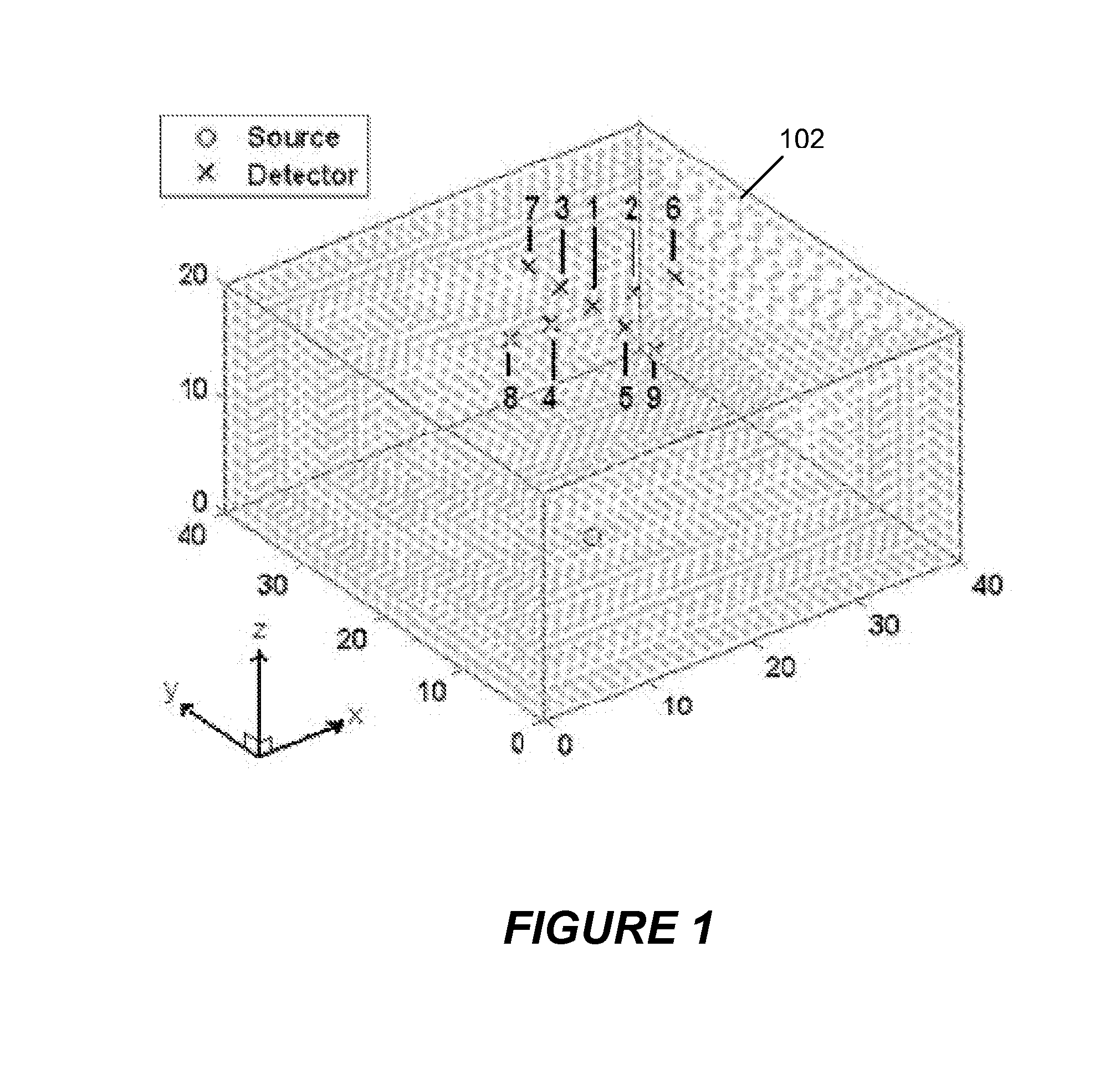
[0015]Shown in FIG. 1 is a schematic image of a sample 102 comprising a volume of interest (VOI) which might be selected for examination using the present invention. For ease of description, the VOI shown in the figure has the shape of a right angle parallelepiped, but those skilled in the art will recognize that the actual shape may be different. In this example, the volume is to be scanned using one source location (indicated by a “O” in the figure) and nine detector locations (each indicated by an “X”) in the figure. As shown, the detectors are arranged in a “cross-shape” geometry, and the detectors and the source are positioned, respectively, on opposite sides of the sample. Relative to the Cartesian coordinate system shown in the figure, tomographic data is collected by raster-scanning this configuration over a two-dimensional region of interest in the x-y plane.
[0016]The construction of an optical fluorescence model using the present invention does not use values for absorptio...
PUM
 Abstract
Description
Claims
Application Information
 - R&D
- Intellectual Property
- Life Sciences
- Materials
- Tech Scout
- Unparalleled Data Quality
- Higher Quality Content
- 60% Fewer Hallucinations
Browse by: Latest US Patents, China's latest patents, Technical Efficacy Thesaurus, Application Domain, Technology Topic, Popular Technical Reports.
© 2025 PatSnap. All rights reserved.Legal|Privacy policy|Modern Slavery Act Transparency Statement|Sitemap|About US| Contact US: help@patsnap.com


