Exhaust Purifier for Internal Combustion Engine

a technology of exhaust gas purifier and internal combustion engine, which is applied in the direction of exhaust treatment electric control, electrical control, separation process, etc., can solve the problems of increasing the temperature of the exhaust gas purifying catalyst, increasing the burning of reducing agents, etc., and lowering the temperature of the exhaust gas and the catalyst. , the effect of lowering the injection amoun

Inactive Publication Date: 2009-01-08
TOYOTA JIDOSHA KK +1
View PDF5 Cites 7 Cited by
  • Summary
  • Abstract
  • Description
  • Claims
  • Application Information

AI Technical Summary

Benefits of technology

[0016]Further preferably, the control unit restricts an amount of fuel injection from the fuel injection valve, as control of the parameter.
[0017]In the internal combustion engine and the exhaust gas purifying apparatus, as the amount of fuel injection from the fuel injection valve is decreased, the temperature of the exhaust gas and the catalyst is accordingly lowered. The injection amount is thus restricted as in the present invention, so that the injection amount is decreased as compared with a case where the injection amount is not restricted, and the temperature of the exhaust gas is lowered. Then, the temperature of the catalyst is lowered, and it is less likely that the upper limit of the allowable range is exceeded. In this manner, according to the present invention, the effect of the invention described above is reliably obtained.
[0018]Further preferably, when at least one of the temperature of the addition valve and the corresponding value is high, the control unit restricts the amount of fuel injection to a larger extent than when at least one of the temperature of the addition valve and the corresponding value is low.
[0019]Here, as the injection amount is restricted to a larger extent, an amount of lowering in the temperature of the exhaust gas and the catalyst as a result of restriction becomes greater. In this regard, in the present invention, when at least one of the temperature of the addition valve and the value corresponding thereto is high (when the degree of increase in the addition amount is great and an amount of increase in the temperature of the catalyst is great), the injection amount is restricted to a larger extent than when at least one of the temperature of the addition valve and the value corresponding thereto is low. In this manner, the degree of restriction of the injection amount is varied in accordance with at least one of the temperature of the addition valve and the value corresponding thereto, so that undue lowering in the engine output due to excessive restriction of the injection amount can be suppressed when at least one of the temperature of the addition valve and the value corresponding thereto is relatively low. In addition, when at least one of the temperature of the addition valve and the value corresponding thereto is high, such a situation that restriction of the injection amount is insufficient (the injection amount is great) and the temperature of the catalyst consequently exceeds the upper limit of the allowable range can be suppressed.
[0020]Further preferably, the control unit decreases an amount of fuel injection from the fuel injection valve, as control of the parameter.
[0021]In the internal combustion engine and the exhaust gas purifying apparatus, as the amount of fuel injection from the fuel injection valve is decreased, the temperature of the exhaust gas and the catalyst is accordingly lowered. The injection amount is thus decreased as in the present invention, so that the temperature of the exhaust gas is lowered as compared with a case where the injection amount is not decreased. Then, the temperature of the catalyst is lowered, and it is unlikely that the upper limit of the allowable range is exceeded. In this manner, according to the present invention, the effect of the invention described above is reliably obtained.

Problems solved by technology

On the other hand, the increased reducing agent burns, and the temperature of the exhaust gas purifying catalyst is raised by the heat generated during the combustion.

Method used


Image

  • Exhaust Purifier for Internal Combustion Engine
  • Exhaust Purifier for Internal Combustion Engine
  • Exhaust Purifier for Internal Combustion Engine

Examples


first embodiment

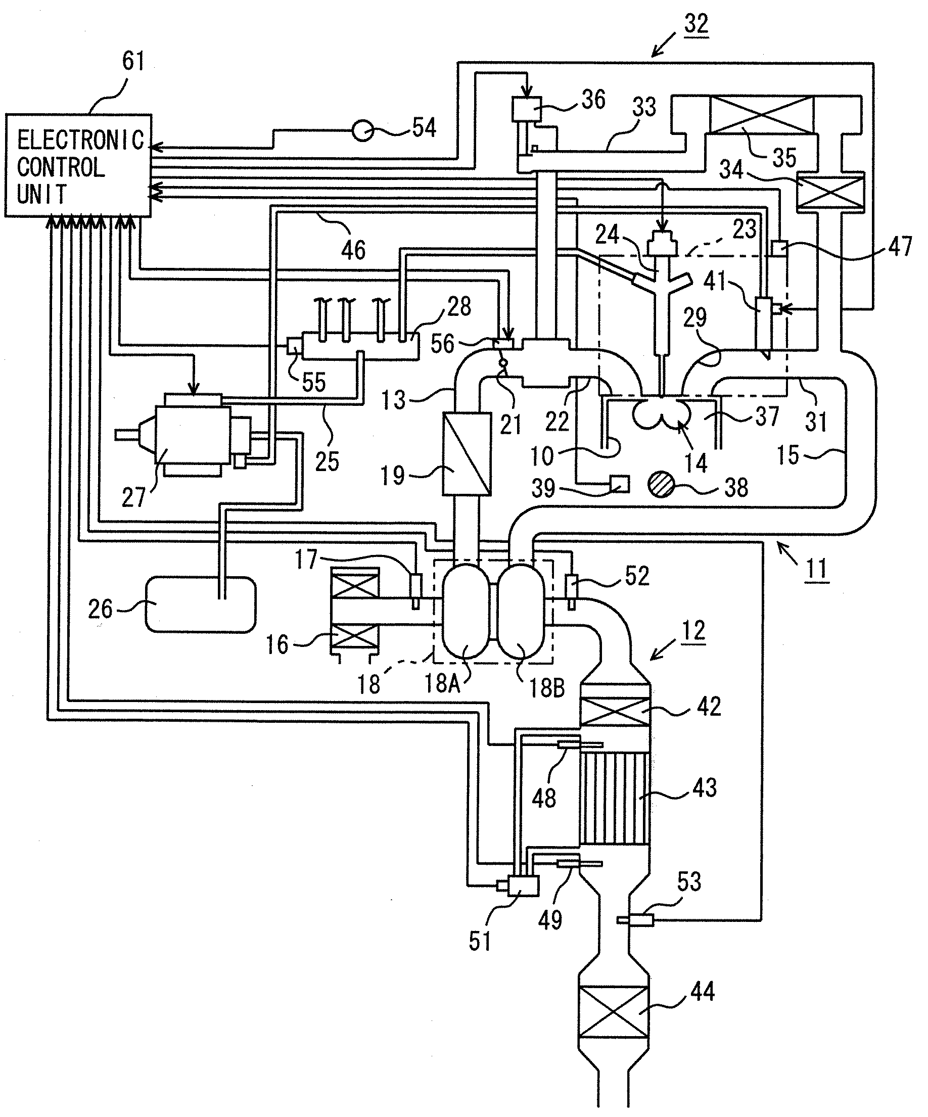
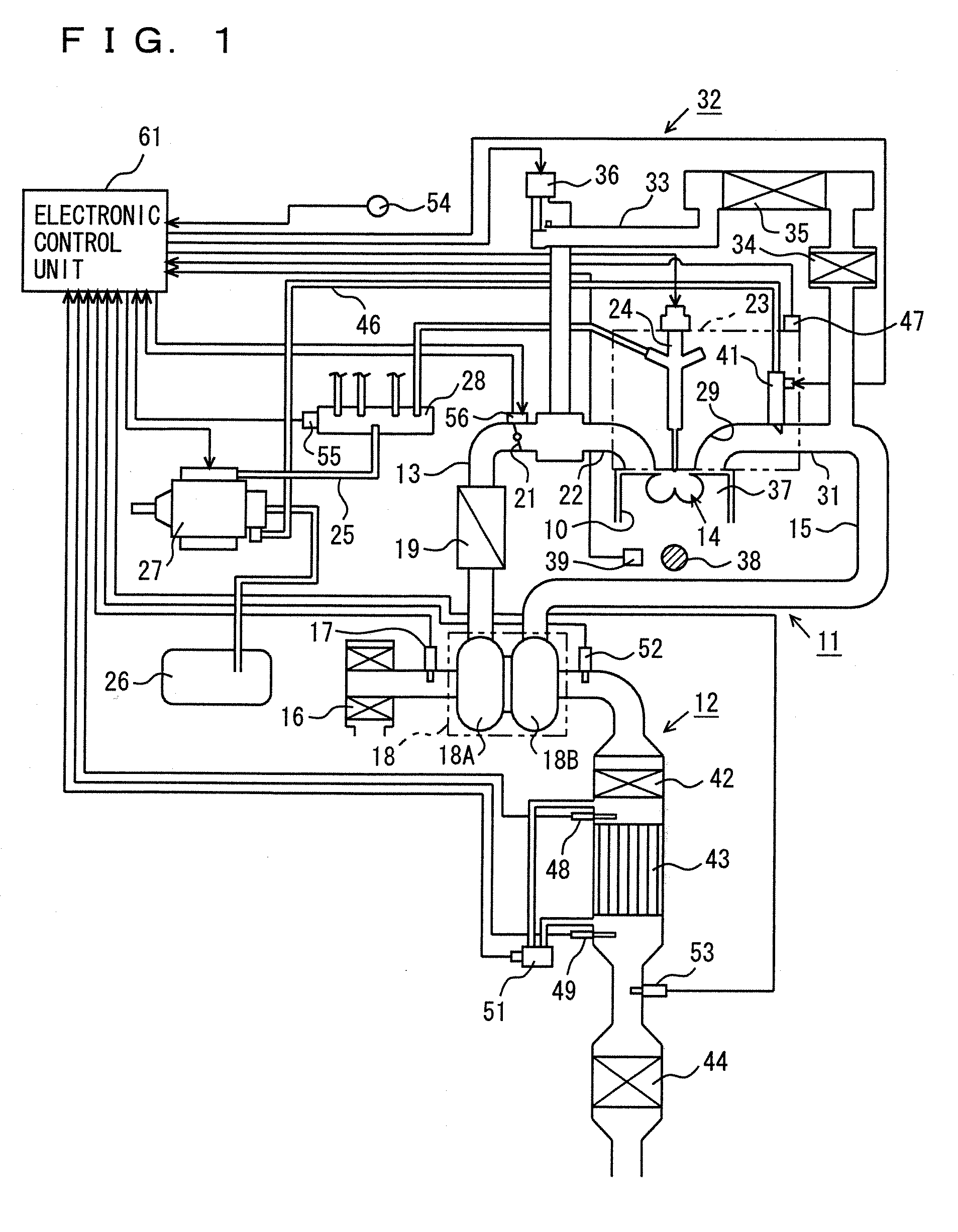
[0033]A first embodiment implementing the present invention will be described hereinafter with reference to FIGS. 1 to 5. FIG. 1 shows a configuration of a multi-cylinder diesel engine (hereinafter, simply referred to as an engine) 11 serving as an internal combustion engine to which the present embodiment is applied and an exhaust gas purifying apparatus 12. FIG. 2 shows a schematic plan view of engine 11.

[0034]Engine 11 generally includes an intake pipe 13, a combustion chamber 14 for each cylinder 10, and an exhaust pipe 15. An air cleaner 16 purifying air taken in intake pipe 13 is provided in a most upstream portion of intake pipe 13. In engine 11, an airflow meter 17 for detecting a flow rate of air in intake pipe 13, a compressor 18A of a turbo charger 18, an intercooler 19, and an intake air throttle valve 21 are sequentially arranged toward the intake air downstream side of air cleaner 16. Intake pipe 13 is branched at an intake manifold 22 provided on the intake air downst...

second embodiment

[0083]A second embodiment implementing the present invention will now be described with reference to FIGS. 6 to 8. The second embodiment is different from the first embodiment in that the target injection amount is decreased, instead of restricting the same, for control such that the catalyst bed temperature does not exceed the upper limit of the allowable range with the increase in the addition amount of the reducing agent. As the configuration of engine 11 and exhaust gas purifying apparatus 12 is the same as in the first embodiment, description thereof will not be repeated.

[0084]FIG. 6 is a flowchart showing a specific procedure for injection amount decrease processing. Electronic control unit 61 executes a series of processing shown in the flowchart as processing to be performed every prescribed time.

[0085]In the injection amount decrease processing, initially in step 310, electronic control unit 61 reads engine coolant temperature THW detected by coolant temperature sensor 47 a...


PUM

PropertyMeasurementUnit
temperatureaaaaaaaaaa
concentrationaaaaaaaaaa
bed temperatureaaaaaaaaaa

Abstract

An addition valve is provided upstream of an exhaust gas purifying catalyst (NOx catalyst) in an exhaust pipe and in the vicinity of a water jacket in a cylinder head, in addition to a fuel injection valve injecting fuel for combustion in a combustion chamber. The addition valve injects a reducing agent in an addition amount in accordance with an operation state of an engine. Using an engine coolant temperature correlated to a temperature of the addition valve, a target addition interval of the addition valve is made shorter with increase in the engine coolant temperature, so that the addition amount is increased (step 130). The temperature of the exhaust gas purifying catalyst (catalyst bed temperature) is raised as a result of increase in the addition amount. Here, a target injection amount of fuel, representing one of parameters other than the addition amount that affect the catalyst bed temperature, is restricted by using an injection amount upper limit, such that the catalyst bed temperature does not exceed an upper limit of an allowable range (steps 240, 250).

Description

TECHNICAL FIELD[0001]The present invention relates to an exhaust gas purifying apparatus of an internal combustion engine, configured to provide an addition valve upstream of an exhaust gas purifying catalyst in an exhaust pipe for injection of a reducing agent, in addition to a fuel injection valve injecting fuel burnt in a combustion chamber of the internal combustion engine.BACKGROUND ART[0002]In an internal combustion engine operating by burning an air-fuel mixture at a high air-fuel ratio (lean atmosphere) in a wide operation region, such as a diesel engine, generally, an NOx catalyst attaining a function to purify a nitrogen oxide NOx in the exhaust gas is provided in an exhaust pipe thereof. As the NOx catalyst, for example, a catalyst carrying both an NOx absorbent capable of absorbing nitrogen oxide NOx in the presence of oxygen and a precious metal catalyst (precious metal) capable of oxidizing hydrocarbon HC on a honeycomb structure (carrier) made of porous ceramics is ad...

Claims


Application Information

Patent Timeline
Patent Type & Authority Applications(United States)
IPC IPC(8): F01N9/00
CPCB01D53/9431F01N13/0097F01N3/035F01N3/0814F01N3/0821F01N3/0842F01N3/0871F01N3/106F01N11/002F01N2260/024F01N2510/06F01N2560/06F01N2560/08F01N2560/14F01N2610/03F01N2610/1493F01N2900/08F01N2900/1811F02D41/027F02D2041/0265Y02T10/47F01N13/009B01D2251/20Y02T10/40
Inventor KAMEDA, KAZUAKI
Owner TOYOTA JIDOSHA KK
Why Eureka
Try Eureka