Method and arrangement for cleaning optical surfaces in plasma-based radiation sources

Active Publication Date: 2009-01-15
USHIO DENKI KK
View PDF7 Cites 32 Cited by
  • Summary
  • Abstract
  • Description
  • Claims
  • Application Information

AI Technical Summary

Benefits of technology

[0015]It is the primary object of the invention to find a novel possibility for in-situ cleaning of the optical surfaces of reflection optics which are contaminated by the debris emitted by a hot plasma in a plasma-based EUV radiation source so as to allow an inte

Problems solved by technology

These particles (debris) are damaging primarily to the collector optics and condenser optics near the plasma which are constructed for the EUV range as reflection optics with sensitive surfaces, whether they are normal-incidence multilayer mirrors or grazing-incidence metal mirrors.
In either case, the surfaces are degraded by the impinging debris, above all in that debris particles are deposited on the surface and reduce reflectivity.
Deposits of this kind alter the surface characteristics and reduce the reflectivity of the optics relatively quickly.
However, the hot filaments are disadvantageous in that they must likewise be replaced at regular intervals and even cause contamination through evaporation.
There remains the difficulty of generating the radicals with sufficient unifo

Method used


Image

  • Method and arrangement for cleaning optical surfaces in plasma-based radiation sources
  • Method and arrangement for cleaning optical surfaces in plasma-based radiation sources
  • Method and arrangement for cleaning optical surfaces in plasma-based radiation sources

Examples


Example

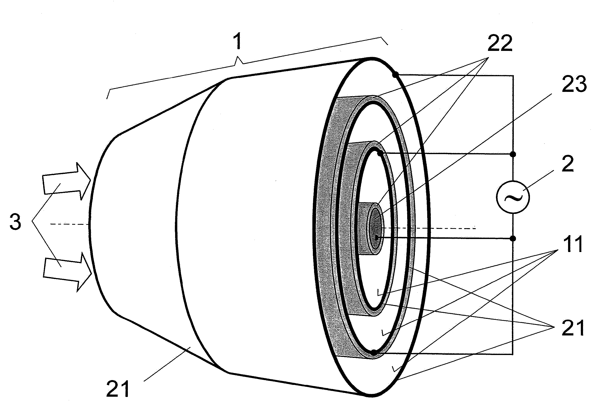
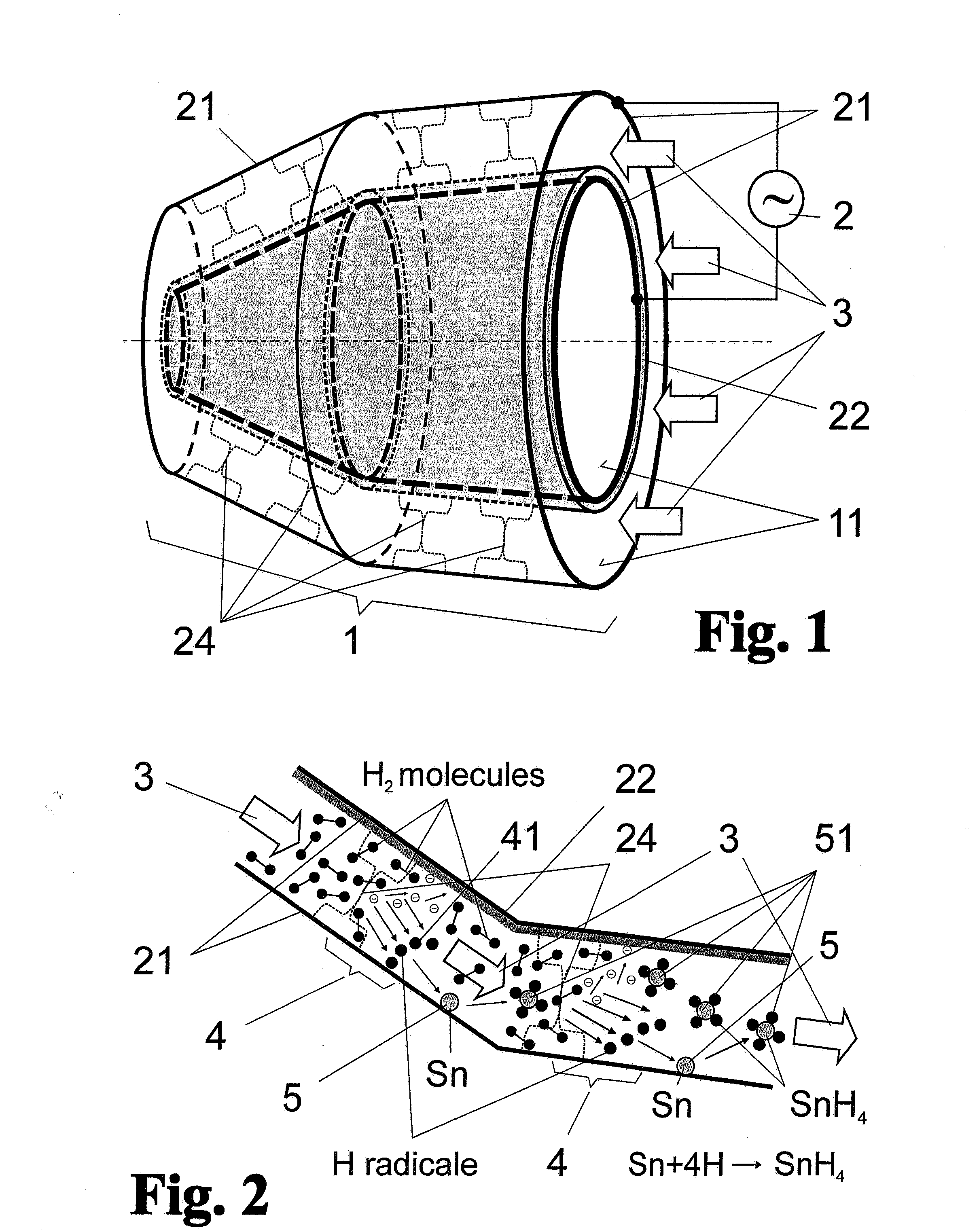
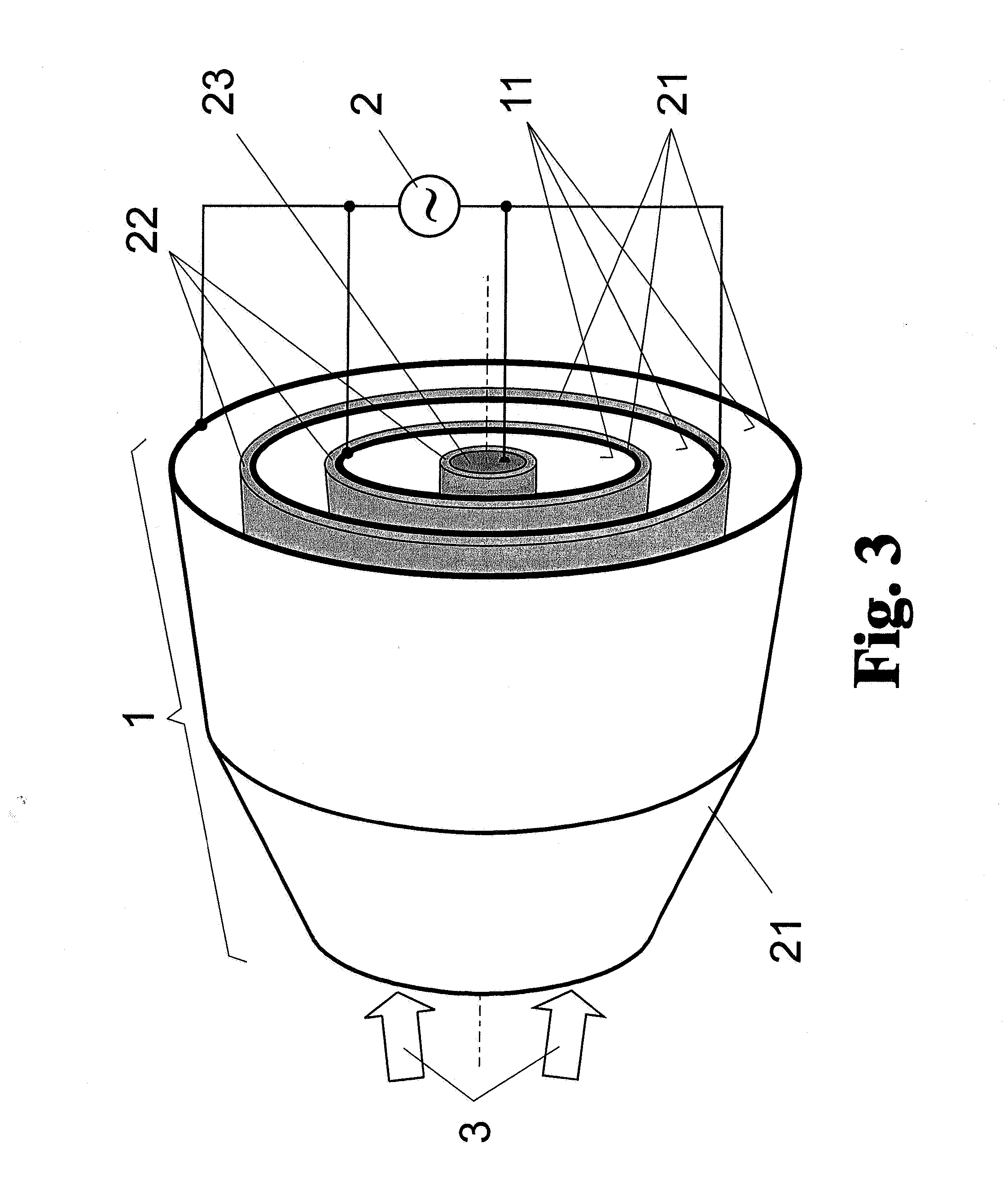
[0044]As is shown schematically in FIG. 1 for a nested, grazing-incidence collector 1, an arrangement for cleaning the optical surfaces of reflection optics which are contaminated in a lithographic exposure device by debris emitted by a hot plasma in a plasma-based EUV radiation source is basically formed of two rotationally symmetric, collinearly arranged mirror surfaces 11 which form metal surface electrodes 21 at the same time and are connected, as such, to an AC voltage source 2. A dielectric barrier layer 22 which is arranged to the rear of the mirror surface 11—because the mirror surfaces 11 to be kept clear are on the inner side of the rotationally symmetric surface electrodes 21—is arranged between the two surface electrodes 21. Accordingly, a dielectrically impeded discharge is possible between the two surface electrodes 21 when voltage is applied.

[0045]The dielectrically impeded discharge, which was already described by Werner von Siemens in 1857 as a “silent electrical di...


PUM

PropertyMeasurementUnit
Thicknessaaaaaaaaaa
Electric potential / voltageaaaaaaaaaa

Abstract

The invention is directed to a method and an arrangement for cleaning optical surfaces of reflection optics which are arranged in a plasma-based radiation source or exposure device arranged downstream and contaminated by debris particles emitted by a hot plasma of the radiation source. It is the object of the invention to find a novel possibility for in-situ cleaning of the optical surfaces of reflection optics which are contaminated by debris in plasma-based radiation sources so as to allow an integrated generation of known gas radicals and the isotropic distribution thereof on the contaminated optical surfaces. According to the invention, this object is met in that the gas radicals are generated by dielectrically impeded discharge between two surface electrodes along the entire optical surface. The gas radicals are generated almost exclusively by electron transfer on at least one barrier layer which covers the entire surface of at least one of the surface electrodes, an AC voltage in the Hz to kHz range is applied to the surface electrodes for periodically eliminating the charge polarization at the barrier layer so that a cold plasma is generated continuously and the deposited debris particles are removed as gaseous reaction products by the gas flow guided over the optical surface.

Description

CROSS-REFERENCE TO RELATED APPLICATION[0001]This application claims priority of German Application No. 10 2007 033 701.0, filed Jul. 14, 2007, the complete disclosure of which is hereby incorporated by reference.BACKGROUND OF THE INVENTION[0002]a) Field of the Invention[0003]The invention is directed to a method and an arrangement for cleaning optical surfaces of reflection optics which are contaminated in a lithographic exposure device by debris emitted by a hot plasma of a plasma-based EUV radiation source, particularly of collector optics in extreme ultraviolet (EUV) high-power radiation sources for semiconductor lithography.[0004]b) Description of the Related Art[0005]EUV radiation is usually generated by thermal radiation sources, particularly by the generation of dense, hot plasmas which are typically based on laser-produced plasma (LPP) or gas-discharge plasma (GDP) and emit isotropically in space. Therefore, for application of EUV radiation, collecting optics are arranged ne...

Claims


Application Information

Patent Timeline
IPC IPC(8): B08B7/00
CPCB08B5/00G03F7/70175G03F7/70483H05H1/24G03F7/70933G03F7/70983G03F7/70925H05H1/245H05H2245/40H01J37/32
Inventor SCHRIEVER, GUIDO
Owner USHIO DENKI KK
Why Eureka
Try Eureka