Drug eluting medical devices having porous layers

a technology of porous layers and medical devices, applied in the field of medical devices, can solve the problems of inferior cell adhesion and growth relative to textured surfaces, smooth surfaces by their nature do not allow cell in-growth, etc., and achieve the effects of reducing or selective retention of therapeutic agents, improving cell adhesion, and improving cell proliferation

Inactive Publication Date: 2009-01-29
BOSTON SCI SCIMED INC
View PDF99 Cites 56 Cited by
  • Summary
  • Abstract
  • Description
  • Claims
  • Application Information

AI Technical Summary

Benefits of technology

[0008]Depending on the embodiment that is practiced, advantages of the present invention may include one or more of the following, among others: (a) reduced or selective retention of therapeutic agent(s), (b) improved cell adh...

Problems solved by technology

Moreover, smooth surfaces by their nature do not allow for cell in-growth.
Furthermore, sm...

Method used


Image

  • Drug eluting medical devices having porous layers
  • Drug eluting medical devices having porous layers

Examples


example 1

[0081]Stainless steel stents, 24 mm, 4 mm diameter, Liberté™, available from Boston Scientific, are cleaned with an RF oxygen plasma for 5 minutes to remove surface contaminants. Polyethyleneimine (PEI), poly(allylamine hydrochloride) (PAH), and poly(sodium-4-styrene sulfonate) (PSS) are available from Aldrich. Each of these polyelectrolytes is provided in solutions having a concentration of 1 mM polyelectrolyte and 0.8 M NaCl. Negatively charged sulfate-stabilized polystyrene (PS) spheres of diameter 330 nm are available from MicroPartikel, Berlin, Germany. The PS particle suspension is 0.1% m / m in pure water. Using the different solutions, an initial four layers of PEI-PAH-PSS-PAH are coated on the stent surface by dipping for 10 minutes in the separate solutions and rinsing twice in pure water for 10 minutes. The fifth layer is made by dipping the stent into the solution having the PS spheres. After this, the stent is rinsed with water and dipped again in the PAH solution. This s...

example 2

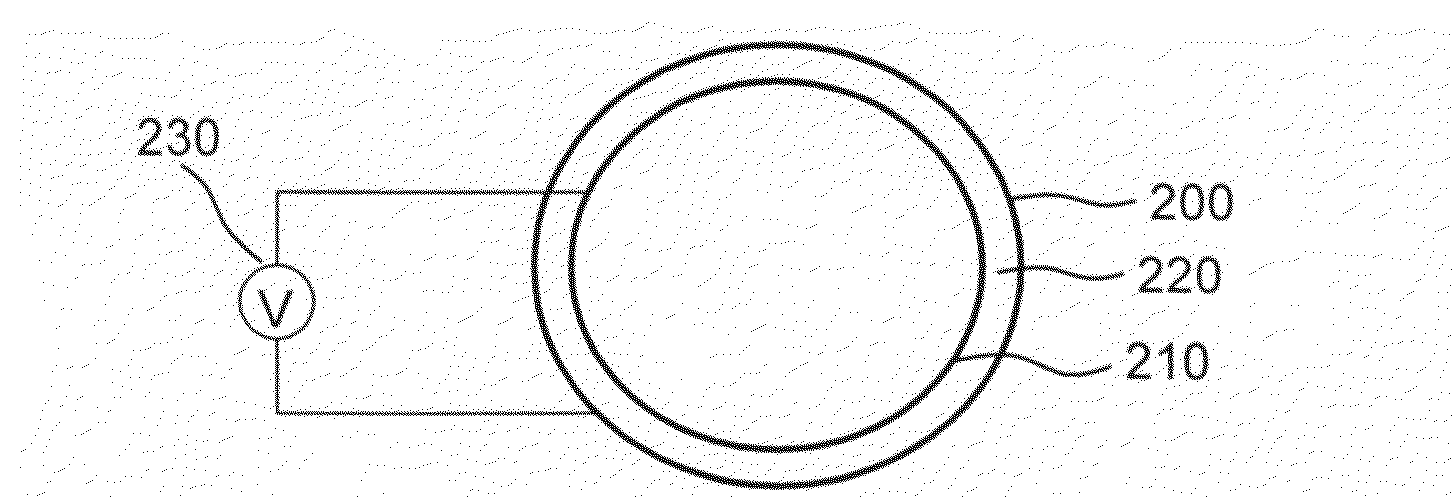
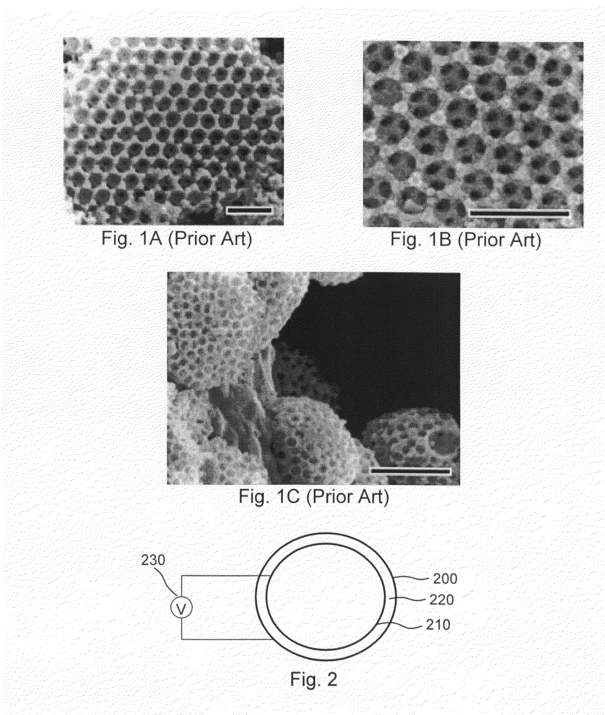
[0082]Stainless steel stents, 24 mm, 4 mm diameter, Liberté™, available from Boston Scientific, are cleaned with an RF oxygen plasma for 5 minutes to remove surface contaminants. Negatively charged sulfate-stabilized PS spheres of diameter 330 nm are available from MicroPartikel, Berlin, Germany. (Alternatively, negatively charged PS spheres of 975±10 nm diameter may be provided by Ikerlat Polymers as described in M. Yoldi et al., J. Mater. Sci., 41 (2006) 2965-2969.) Following procedures along the lines described in M. Yoldi et al., and using an electrochemical cell like that illustrated in FIG. 2, an aqueous colloidal dispersion of negatively charged polystyrene spheres in an aqueous-ethanolic medium is deposited on the interior surface of the stent, which corresponds to the positively charged electrode of the electrochemical cell, by applying a suitable DC voltage for a time sufficient to create a multilayer colloidal crystal (e.g., one having approximately 20 layers). Once the c...

example 3

[0083]Stents in accordance with Example 1 and Example 2 are subjected to sol-gel processing by immersing the stents for 12 hours in a solution of 2 wt % TEOS (tetra-ethoxy-silane), 88 wt % ethanol, 9 wt % water, and 1 wt % ammonium hydroxide. The stents are then calcinated at 540° C. for 8 hours to remove the organic components and cooled overnight in the oven to room temperature, yielding stents with a multi-layer structure of hollow silica spheres.


PUM

PropertyMeasurementUnit
Diameteraaaaaaaaaa
Diameteraaaaaaaaaa
Thicknessaaaaaaaaaa

Abstract

In accordance with an aspect of the invention, implantable or insertable medical devices are provided that comprise (a) a substrate and (b) a porous layer comprising close packed spherical pores disposed over the substrate. The porous layer may also comprise a therapeutic agent. In another aspect, the present invention provides methods of forming implantable or insertable medical devices. These methods comprise forming a predecessor structure that comprises (i) a substrate over which is disposed (ii) an assembly of microspheres. This assembly of microspheres is then used as a template for the formation of a porous layer, which may be subsequently loaded with a therapeutic agent.

Description

FIELD OF THE INVENTION[0001]This invention relates to medical devices, and more particularly to drug eluting medical devices having porous layers.BACKGROUND OF THE INVENTION[0002]The in vivo delivery of therapeutic agents within the body of a patient is common in the practice of modern medicine. In vivo delivery of therapeutic agents is often implemented using medical devices that may be temporarily or permanently placed at a target site within the body. These medical devices can be maintained, as required, at their target sites for short or prolonged periods of time, delivering biologically active agents at the target site.[0003]In accordance with certain delivery strategies, a therapeutic agent is provided within or beneath a biostable polymeric layer that is associated with a medical device. Once the medical device is placed at the desired location within a patient, the therapeutic agent is released from the medical device with a profile that is dependent, for example, upon the n...

Claims


Application Information

Patent Timeline
IPC IPC(8): B32B1/08B05D3/00B32B3/26
CPCA61L31/082A61L31/146A61L31/16A61L31/148A61L2300/608A61L31/10A61L31/022Y10T428/13Y10T428/249994
Inventor ATANASOSKA, LILIANAWARNER, ROBERT W.ARNEY, MICHAEL S.WEBER, JAN
Owner BOSTON SCI SCIMED INC
Why Eureka
Try Eureka