Induction heating element made of glassy carbon, heating device and heater

Inactive Publication Date: 2009-03-19
KOBE STEEL LTD
View PDF2 Cites 2 Cited by
  • Summary
  • Abstract
  • Description
  • Claims
  • Application Information

AI Technical Summary

Benefits of technology

[0019]The glass-like carbon induction heating element of the invention of the application is formed such that the heating element has the infrared radiation characteristic that the ratio (E1 / E2) of the infrared radiation intensity (E1) of the opposed face to the object-to-be-heated to the infrared radiation intensity (E2) of the non-opposed face to the object-to-be-heated exceeds 1.2. Thus, the heating element is used as an induction heating element for a heating apparatus, thereby temperature increase of the glass-like carbon induction heating element itself, and radiation of infrared rays to the object-to-be-heated by the opposed face to the object-to-be-heated of the induction heating element 11, which corresponds to heat radiation from the induction heating element, can be performed in a well-balanced manner, consequently high heating efficiency can be obtained compared with a heating element, which does not have such an infrared radiation characteristic ((E1 / E2)>1.2), even at the same input power.
[0020]Moreover, according to the heating apparatus of the invention of the application, since the apparatus has the glass-like carbon induction heating element endowed with the infrared radiation characteristic, and the high frequency induction coil is applied with a current so that the object-to-be-heated is heated by infrared rays radiated from the glass-like carbon induction heating element, excellent heating efficiency can be exhibited.
[0021]The heater of the invention of the application is configured such that a glass-like carbon induction heating reactor tube or a glass-like carbon induction heating vessel, inside which an object-to-be-heated is stored, is covered with a covering member made up of carbon fiber low-density molding at a portion facing the high frequency induction coil in an outer circumferential face of the tube or vessel, that is, a portion to be at high temperature in the outer circumferential face. Since the covering member made up of the carbon fiber low-density molding prevents oxygen in air atmosphere from being diffused to neighborhood of the portion to be at high temperature by induction heating in the outer circumferential face, in addition, carbon fiber itself reacts with hydrogen, oxygen concentration can be decreased in the portion to be at high temperature by induction heat generation in the outer circumferential face, thereby the glass-like carbon induction heating reactor tube itself or the glass-like carbon induction heating vessel itself can be effectively prevented from being consumed by oxidation. Moreover, since the covering member made up of the carbon fiber low-density molding has extremely small heat conductivity compared with glass-like carbon, heat radiation from the portion to be at high temperature by induction heat generation in the outer circumferential face of the glass-like carbon induction heating reactor tube or the glass-like carbon induction heating vessel can be effectively prevented. Moreover, the covering member made up of carbon fiber low-density molding can be easily exchanged as needed.
[0022]Consequently, in the heater of the invention of the application, the glass-like carbon induction heating reactor tube or the glass-like carbon induction heating vessel, which is disposed in air atmosphere, and has the object-to-be-heated stored in the inside, is covered with the covering member made up of carbon fiber low-density molding at the portion facing the high frequency induction coil in the outer circumferential face of the tube or vessel, thereby even if the outer circumferential face is exposed to the air, the tube or vessel is able to have oxidation resistance to air atmosphere at low cost compared with a tube or vessel applied with oxidation resistant coating of silicon carbide or the like on an outer circumferential face, and have heat-radiation protection performance, and consequently is can be used at higher temperature.

Problems solved by technology

Furthermore, when the method is used for the heating treatment of the silicon wafer in the semiconductor integrated circuit manufacturing process, the heating element is required to be extremely low in production of impurities of metal and the like.
Among them, the metal material had advantages of ease in machining and comparatively low cost, however, it may cause metal impurities, or is problematic in corrosion resistance, therefore the metal material is not suitable for the semiconductor integrated circuit manufacturing process.
However, the heating element has been pointed out with a problem that such coating is separated, causing formation of particles, or a problem that particles are produced from the inside through defects in the coating.
On the other hand, glass-like carbon is a conductive material and usable for a material of the induction heating element, in addition, excellent in heat resistance, corrosion resistance, and gas impermeability, and low in dust production.
However, the usual glass-like carbon induction heating element has not necessarily provided a sufficient result in heating efficiency.
A glass-like carbon induction heating reactor tube or a glass-like carbon induction heating vessel, which is disposed in air atmosphere, and stores an object-to-be-heated in the inside, is limited in use temperature to comparatively low temperature since glass-like carbon does not have sufficient oxidation resistance, and may be consumed by oxidization when it is contacted to oxygen at high temperature.
Furthermore, since the tube or vessel is large in heat radiation from an outer circumferential face, it does not have so high heating efficiency as expected.
However, there is a problem that since the surface of glass-like carbon is chemically inactive, coating is easily separated.
Moreover, while the glass-like carbon is inevitably subjected to temperature change since it is used for a heating apparatus, generally, glass-like carbon and a coating material are not equal in linear expansion coefficient, therefore a film may be separated due to stress caused by temperature change.
In addition, extremely high cost is required for coating treatment.

Method used


Image

  • Induction heating element made of glassy carbon, heating device and heater
  • Induction heating element made of glassy carbon, heating device and heater
  • Induction heating element made of glassy carbon, heating device and heater

Examples


example 1

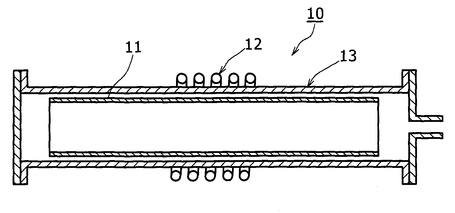
[0059]Next, examples of the glass-like carbon induction heating element of the invention, and the heating apparatus using the heating element are described.

[0060]First, description is made on measurement of infrared emissivity as infrared radiation intensity of each of the opposed and non-opposed faces to the object-to-be-heated of the glass-like carbon induction heating element. For the measurement of infrared emissivity, Fourier transform infrared spectrophotometer JIR-5500 and infrared radiation measurement unit IRR-200 manufactured by JEOL Ltd. was used as an apparatus, and a substrate 3 cm square was used as a specimen (when a heating element itself is not mounted in the apparatus, it is appropriately cut out). As a method of measuring infrared emissivity, spectral radiant intensity (measurement values) of two points (160° C. and 80° C.) in a black-body furnace and the intensity of the specimen were measured, then the intensity and spectral radiant intensity of the black-body (...

example 2

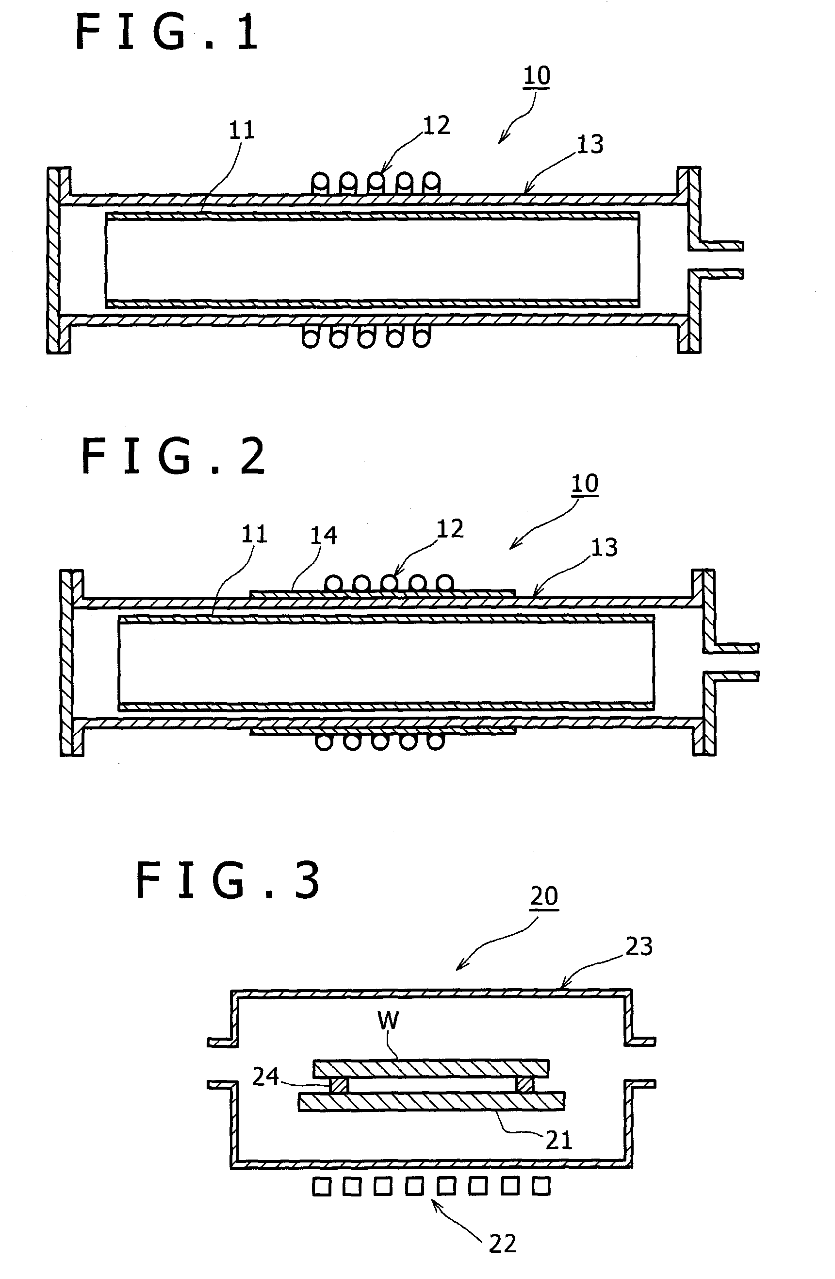
[0073]In the heating apparatus 10′ as shown in FIG. 2, the same glass-like carbon induction heating element as in the example 1-1 was used as the glass-like carbon induction heating element 11, and carbon fiber felt (“KRECA FR” manufactured by Kureha Corporation) 3 mm in thickness was wound on an outer circumferential face of the reactor vessel 13 as the covering member 14. Then, a heating test was performed at the same condition as in the example 1. As a result, 12 sec was taken as time before temperature of a central portion of the inside of the glass-like carbon induction heating element reached 600° C. In addition, heat radiation from a surface of the reactor vessel 13 was prevented, consequently high heating efficiency was able to be obtained compared with that in the example 101 in which the covering member 14 was not provided.

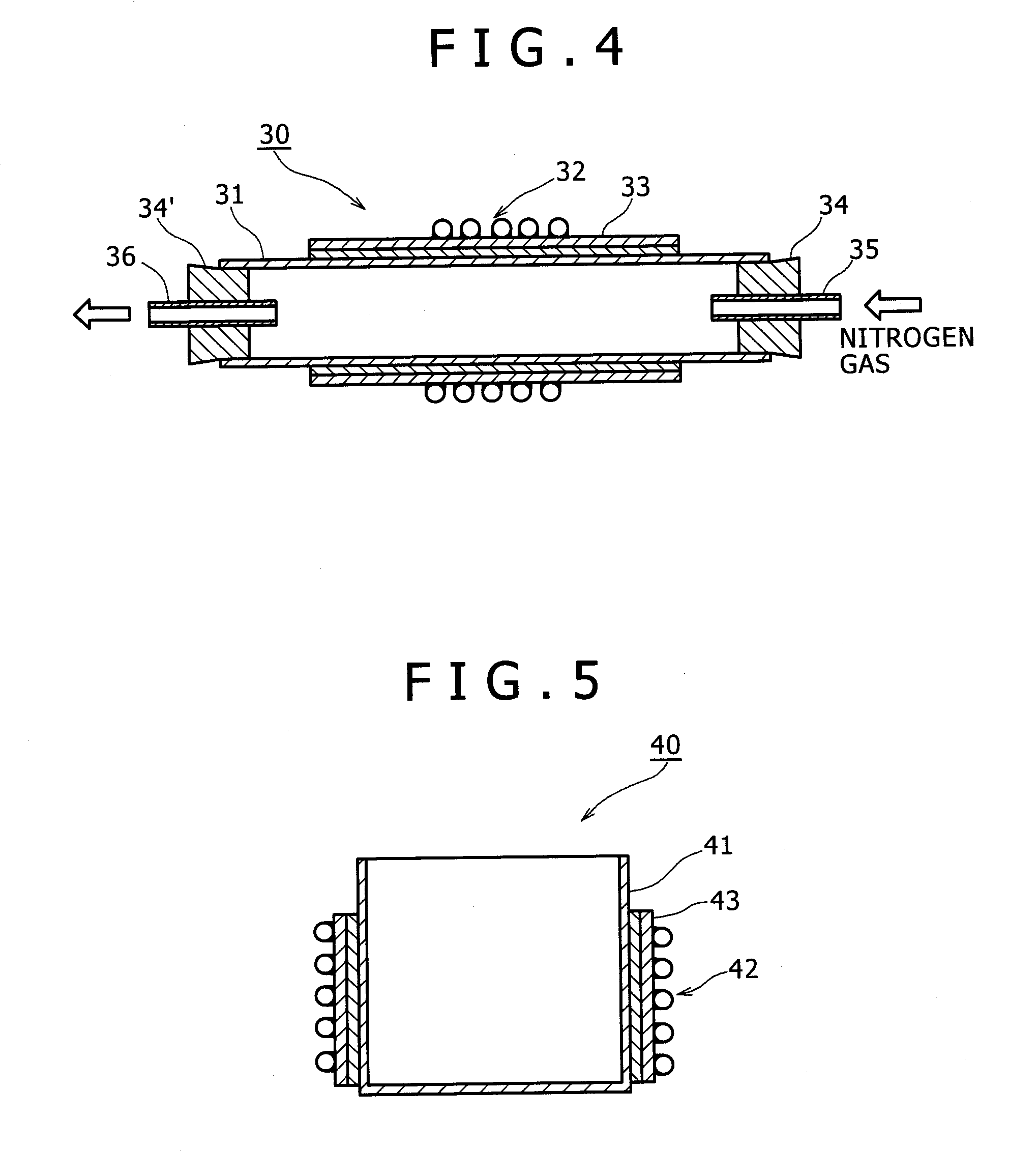
[0074]Next, a heater of the invention is described.

[0075]FIG. 4 is a cross section diagram schematically showing a configuration of a heater according t...

example 3

[0082]Next, an example of the heater of the invention is described below.

[0083]First, for a material resin of glass-like carbon, a commercially available, liquid phenol resin, PL4804 manufactured by Gun-Ei Chemical Industry Co., Ltd. was subjected to heat treatment for 1 hour at 100° C. under reduced pressure to be adjusted in moisture percentage, and then used as the material resin of glass-like carbon.

[0084]Next, for molding of a phenol resin cylindrical body, a centrifugal molding machine was used, which has a cylindrical centrifugal molding die made of stainless steel 60 mm in inner diameter and 600 mm in length. The liquid material resin of 520 g was charged in the centrifugal molding die, then the material resin was cured by holding the resin for 24 hours at a die surface temperature of 80° C. while the centrifugal molding die was rotated at a speed of 600 revolutions per minute, and consequently the phenol resin cylindrical body was obtained.

[0085]Next, the phenol resin cylin...


PUM


Abstract

A glass-like carbon induction heating element having high heating efficiency and a heating apparatus are provided. A glass-like carbon induction heating element, which inductively generates heat by electromagnetic induction, has an infrared radiation characteristic that a ratio (E1 / E2) of infrared radiation intensity (E1) of an opposed face to an object-to-be-heated to infrared radiation intensity (E2) of a non-opposed face to the object-to-be-heated exceeds 1.2. A heating apparatus has the glass-like carbon induction heating element, and a high frequency induction coil that is disposed outside the glass-like carbon induction heating element for allowing the glass-like carbon induction heating element to inductively generate heat, wherein the high frequency induction coil is applied with a current so that the object-to-be-heated is heated by infrared rays radiated from the glass-like carbon induction heating element.

Description

TECHNICAL FIELD[0001]The present invention relates to a glass-like carbon induction heating element used as a heating element that inductively generates heat by electromagnetic induction when an object-to-be-heated such as silicon wafer is heated, and a heating apparatus using the glass-like carbon induction heating element, and a heater having a glass-like carbon heating reactor tube or an induction heating vessel.BACKGROUND ART[0002]An induction heating method, in which a high frequency induction coil is applied with a current to allow a heating element to inductively generate heat, thereby an object-to-be-heated is heated, is frequently used for applications requiring rapid temperature rise, uniform heating, and excellent temperature response (controllability) and the like, including heating treatment of a silicon wafer in a semiconductor integrated circuit manufacturing process. As typical characteristics required for such a heating element that inductively generates heat by ele...

Claims


Application Information

Patent Timeline
IPC IPC(8): H05B6/02
CPCH01L21/67109H05B6/105H01L21/67115
Inventor HAMAGUCHI, MAKI
Owner KOBE STEEL LTD
Why Eureka
Try Eureka