Porous Electrolessly Deposited Coatings

a technology of electroless coating and porous coating, which is applied in the direction of liquid/solution decomposition chemical coating, cell components, physical/chemical process catalysts, etc., can solve the problems of changing the size of the pores, and achieve the effects of good thermal conductivity, low sulfer content, and longer reaction channel length

Inactive Publication Date: 2009-03-19
VELOCYS CORPORATION
View PDF23 Cites 16 Cited by
  • Summary
  • Abstract
  • Description
  • Claims
  • Application Information

AI Technical Summary

Benefits of technology

[0018]Microchannel reactors are characterized by the presence of at least one reaction channel having at least one dimension (wall-to-wall, not counting catalyst) of 1.0 cm or less, preferably 2.0 mm or less (in some embodiments about 1.0 mm or less) and greater than 100 nm (preferably greater than 1 em), and in some embodiments 50 to 500 μm. A reaction channel is a channel containing a catalyst. Microchannel apparatus is similarly characterized, except that a catalyst-containing reaction channel is not required. Both height and width are substantially perpendicular to the direction of flow of reactants through the reactor. Microchannels are also defined by the presence of at least one inlet that is distinct from at least one outlet—microchannels are not merely channels through zeolites or mesoporous materials. The height and/or width of a reaction microchannel is preferably about 2 mm or less, and more preferably 1 mm or less. The length of a reaction channel is typically longer. Preferably, the length of a reaction channel is greater than 1 cm, in some embodiments greater than 50 cm, in some embodiments greater than 20 cm, and in some embodiments in the range of 1 to 100 cm. The sides of a microchannel are defined by reacti

Problems solved by technology

At least initially the size of the microparticles and the pores is about the same since the particles are oxidized or dissolved

Method used


Image

  • Porous Electrolessly Deposited Coatings
  • Porous Electrolessly Deposited Coatings
  • Porous Electrolessly Deposited Coatings

Examples


example 1 (

REFERENCE)

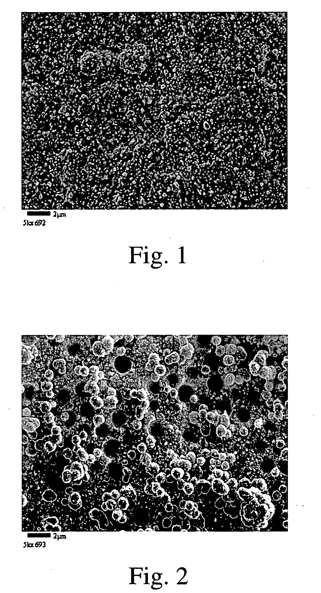
[0041]A solution consisting of Pt(NH3)4(OH)2, (0.2 wt % Pt) and 0.2 wt % N2H4·H2O was prepared. An aluminized alloy 617 coupon was heat-treated at 1050° C. for 10 hours before use. The surface of this coupon was covered by an α—Al2O3 scale. The coupon was hung in the solution at room temperature overnight. 11.4 mg / in2 Pt was plated on the coupon. After that, the Pt plated coupon was put in a new Pt plating solution with the same composition for 3 hours. Next the coupon was cleaned and calcined at 500° C. for 1 h in air. The final Pt loading was 15.7 mg / in2. The SEM micrograph shows that the Pt layer is flat and dense (FIG. 1).

example 2

[0042]An aluminized Inconel 617, heat treated and Pt-plated coupon (15 mg / in2 Pt) was coated with 0.11 mg polystyrene microsphere (1.7 μm) and dried at room temperature. Next the coupon was put in a solution consisting of Pt(NH3)4(OH)2, (0.2 wt % Pt) and 0.2 wt % N2H4·H2O for 20 hours at room temperature. The coupon was then cleaned and calcined at 500° C. for 1 h in air. 11 mg / in2 Pt was plated on the coupon. SEM micrograph shows that the surface Pt layer is porous (FIG. 2). Bimodal pores (1.7 μm and 50-100 nm) are observed.
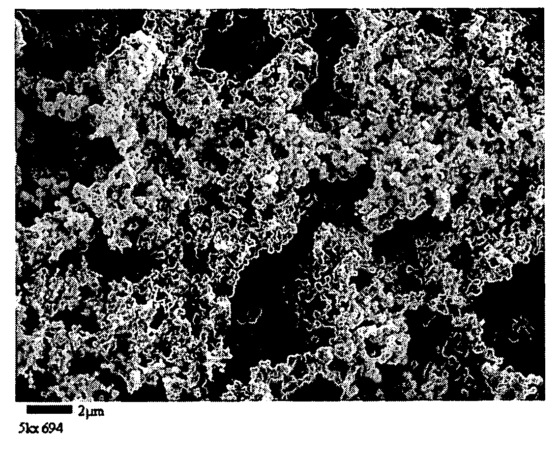
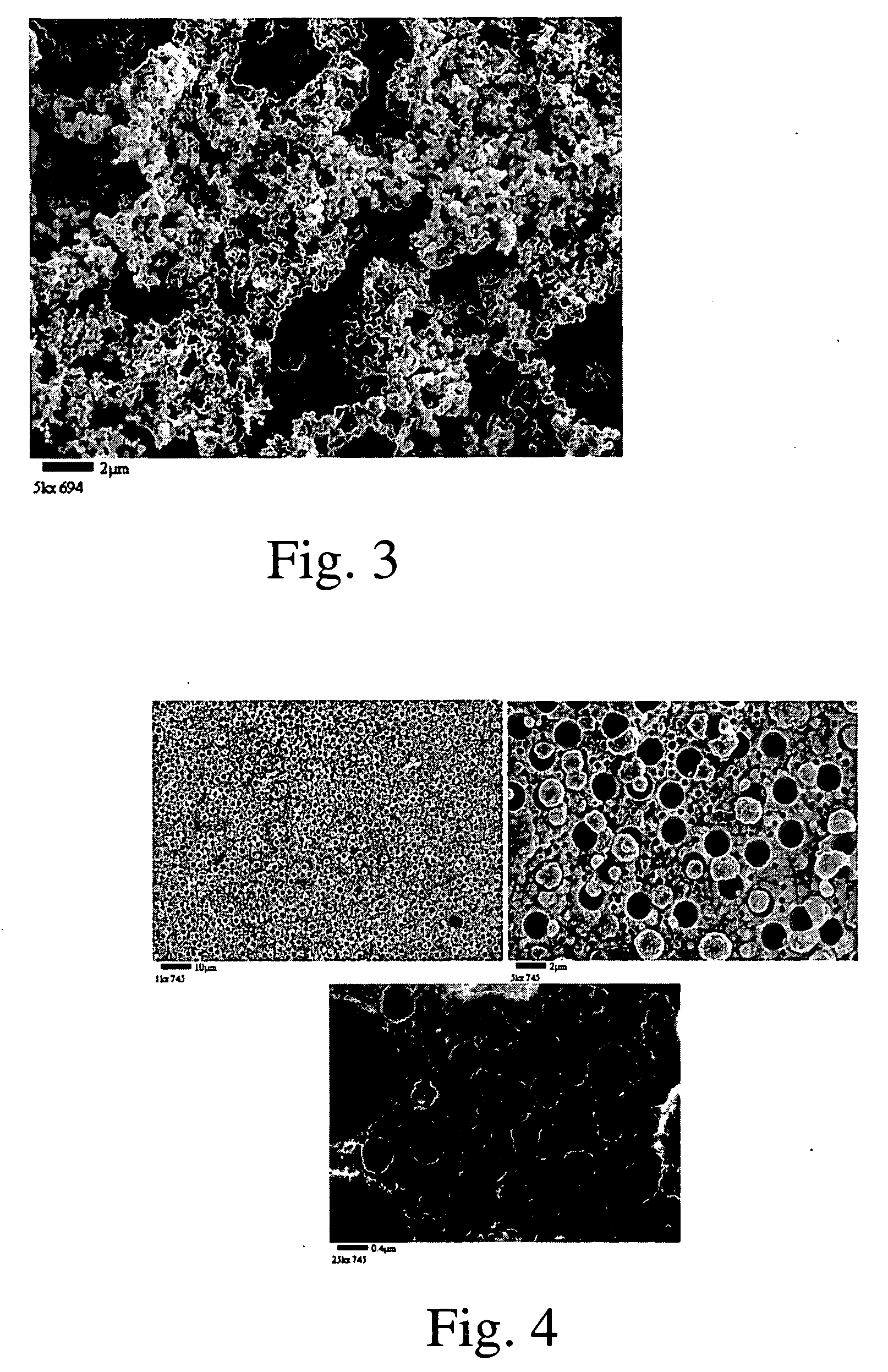
example 3

[0043]An aluminized Inconel 617, heat treated and Pt-plated coupon (15 mg / in2 Pt) was put in a solution consisting of Pt(NH3)4(OH)2, (0.2 wt % Pt), 0.2 wt % N2H4·H2O and 1.0 wt % polystyrene microsphere (1.7 μm) for 20 hours at room temperature. The coupon was then cleaned and calcined at 500° C. for 1 h in air. 12 mg / in2 Pt was plated on the coupon. SEM micrograph shows that the surface Pt layer is very porous (FIG. 3). Pt particle size is in the range of 100 to 200 nm.


PUM

PropertyMeasurementUnit
Volumeaaaaaaaaaa
Contentaaaaaaaaaa

Abstract

A new electroless plating approach to generate a porous metallic coating is described in which a metal is electrolessly deposited on a surface. Microparticles in the metal are removed to leave pores in the metal coating. Another method of forming electroless coatings is described in which a blocking ligand is attached to the surface, followed by a second coating step. The invention includes coatings and coated apparatus formed by methods of the invention. The invention also includes catalyst structures comprising a dense substrate and a porous metal adhered to the dense substrate, which is further characterized by one or more of the specified features.

Description

RELATED APPLICATIONS[0001]In accordance with 35 U.S.C. sect. 119(e), this application claims priority to U.S. Provisional Application No. 60 / 972,210, filed Sep. 13, 2007.INTRODUCTION[0002]There has been a long history of work devoted to forming porous metal coatings. For example, in U.S. Pat. No. 1,628,190, issued in 1927, Raney described a method of making porous nickel by alloying the nickel with aluminum and subsequently dissolving the aluminum to leave porous nickel.[0003]More recently, there has been a great deal of interest in forming metallic coatings in microchannels. Tonkovich et al. in WO 2006 / 127889A2 (PCT / US2006 / 020220, which is incorporated herein as if reproduced in full) describe a variety of microchannel apparatus and numerous ways of forming catalysts on microchannel walls including designs for structured walls that may be subsequently coated with a catalyst. The patent also mentions the use of a polymeric templating agent followed by treatment with a metallic templ...

Claims


Application Information

Patent Timeline
IPC IPC(8): H01M4/86B05D3/10B05D1/36B01J27/24B32B3/30
CPCC23C18/1662Y10T428/24612C23C18/44C23C18/1692Y02E60/50H01M4/8621H01M4/8652H01M4/8825H01M4/9016H01M4/9041H01M4/92
Inventor LONG, RICHARD Q.DALY, FRANCISCHEN, HAIBIAOMAZANEC, TERRY J.
Owner VELOCYS CORPORATION
Why Eureka
Try Eureka