Methods and apparatus for performing flue gas pollution control and/or energy recovery

a technology of flue gas pollution control and energy recovery, applied in heat recovery, emissions prevention, separation processes, etc., can solve the problems of high capital and operating costs, high cost of wesp pollution control devices, and generally very expensive alloys, so as to avoid, eliminate or reduce any need, improve system efficiency, avoid clogging and clumping problems

Active Publication Date: 2009-03-26
MITSUBISHI POWER AMERICAS INC
View PDF18 Cites 46 Cited by
  • Summary
  • Abstract
  • Description
  • Claims
  • Application Information

AI Technical Summary

Benefits of technology

[0016]In addition to using recovered ash as an absorbent additive which is injected into the flue gas stream, various embodiments of the invention use recovered energy from a flue gas cooling element of the system in a way that provides improved system efficiency and not merely cosmetic benefits in terms of the appearance of the smoke stack output. In some but not necessarily all embodiments recovered heat is used to heat one or more flue gas stream additives, e.g., ammonia, supplied to an selective catalytic reactor (SCR), or to heat the condensate from the steam turbine.
[0017]The collected ash which is re-introduced into the flue gas stream may be recovered at any of a variety of points in the system including, for example, from a gas cooler, particulate removal device such as a dry electrostatic precipitator or fabric filter. The collected ash obtained from one or more devices within the system may be stored in an ash hopper or silo prior to re-introduction into the flue gas stream. The novel approach to collecting and using ash, e.g., coal fly ash, turns what was formerly an unwanted waste product into a useful additive which can avoid, eliminate or reduce any need for other absorbent materials being added to the flue gas stream.
[0018]Thus, in the novel system of the invention recycled ash acts as an absorbent and/or reactant m

Problems solved by technology

This gas may contain components which are harmful to the environment, such as oxides of nitrogen (NOx).
Presently for SO3/H2SO4, condensable PM control, power plants often use wet electrostatic precipitator (WESP), or alkali sorbent injection without gas coolers, or a combination of the two to meet emission limits, with high capital and operating costs.
Therefore, all internal components of WESP that are exposed to the gas stream, as well as the flue ducts connecting the WESP must be made of corrosion-resistant material, generally very expensive alloys.
The WESP has become one of the most expensive devices for power plant pollution control.
Additionally, WESP has higher power consumption and significantly reduces plant net output efficiency.
However, they require continuous injection of sorbent material (typically sodium, magnesium or calcium based) and therefore add significantly to plant operating cost.
Sorbent injection also introduces external substance to combustion byproducts (flyash) and therefore can affect its utilization options.
However the cooling has the side effect of producing condensate which tends to be rather corrosive.
This can occur when the amount of dry material in the flu

Method used


Image

  • Methods and apparatus for performing flue gas pollution control and/or energy recovery
  • Methods and apparatus for performing flue gas pollution control and/or energy recovery
  • Methods and apparatus for performing flue gas pollution control and/or energy recovery

Examples


embodiment 500

[0064]FIG. 5 shows an embodiment 500 similar to that of FIG. 4 but with the injection point of the collected fly ash being upstream of the AH 309 at the location of injection nozzle 504 which is inside the duct 508 connecting the SCR 306 to the AH 309. Ash is supplied to nozzle 504 via pipe 502 which in the FIG. 5 embodiment is connected to the ash hoppers on the particulate collection device 424.

embodiment 600

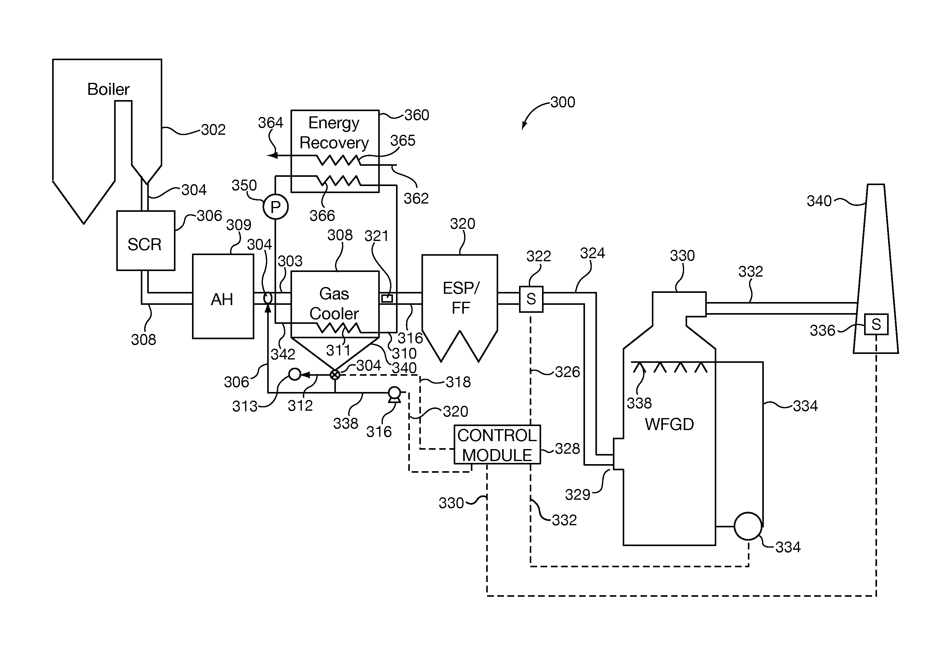
[0065]FIG. 6 illustrates an embodiment 600 which is similar to that of FIG. 3 but with ash being collected in a hopper, represented as a triangle at the bottom of the AH 602, located at the AH 602. Control module 626 controls' a blower 618 and value 614 which is used to control the flow of ash from the hopper at the AH 602 to an injection nozzle 608 via pipe 610. The injection nozzle 608 is located in a duct 606 positioned between the AH 602 and gas cooler 408. Excess ash is discharged from the AH hopper for disposal via pipe 612.

embodiment 700

[0066]FIG. 7 illustrates an embodiment 700 in which ash is collected from hoppers located on the particulate removal device 712 and / or other collection points in the system. The collected ash from device 712 is supplied to an ash silo 724 via control valves 714, 716. The output of an ash hopper 432 on the gas cooler 408 and / or an ash hopper on the AH 309 may, and in some embodiments are, also coupled to an ash input of the ash silo 724 where ash is collected and stored prior to reuse and / or disposal. Control module 738 controls operation of the various valves 714, 716, 726 and blowers 736 via control lines 718, 720, 728, and 730. The output of ash silo 724 is supplied via valve 726 and pipe 706 to an ash injection nozzle 704 and / or to an ash disposal outlet via pipe 732. In the FIG. 7 embodiment, the ash injection nozzle 704 is positioned between the AH 309 and gas cooler 408 in duct 702.

[0067]As discussed above, to facilitate mercury capture, in some embodiment activated carbon is ...


PUM

PropertyMeasurementUnit
Efficiencyaaaaaaaaaa
Corrosion resistanceaaaaaaaaaa
Water absorptionaaaaaaaaaa

Abstract

Methods and apparatus for pollution control which are well suited for use in a coal power plant are described. Ash is collected and injected into the flue gas stream at a location upstream of a cooling module. The ash acts as an absorbent and/or reactant material onto which condensate may condense. By re-introducing ash to keep the condensation forming wet areas within the system, lower cost materials which are less corrosion resistant than needed for wet operating conditions can be used. Mercury recovery and SO3 removal is facilitated by the cooling process and re-introduction of collected ash. Activated carbon and/or an alkali absorbent material may be added. Use of a dry ESP and/or fabric filter as opposed to a wet ESP for particulate collection leads to cost benefits. Energy recovered by the cooling of the flue gas may be re-used to heat turbine condensate leading to improved energy efficiency.

Description

FIELD OF THE INVENTION[0001]This invention relates to flue gas systems, e.g., methods and apparatus for processing flue gas streams for pollution control purposes and / or energy recovery.BACKGROUND OF INVENTION[0002]Coal is an abundant energy source and is expected to remain the dominant fuel for power generation at least through the first half of this century. Today coal-fired power plants must meet stringent environmental requirements with regard to the byproducts they produce.[0003]One of the byproducts of power plants and turbine engines is exhaust gas, commonly known as flue gas. This gas may contain components which are harmful to the environment, such as oxides of nitrogen (NOx). The production of NOx can occur when fossil fuels are combusted such as in refinery heaters, steam boilers, etc.[0004]Plants which burn coal and / or other fuels in many cases are required to control SO2, NOx, and CO and particulate matter. In addition on limits to these byproducts, modern plants may be...

Claims


Application Information

Patent Timeline
IPC IPC(8): F23J15/06F23C1/12
CPCB01D53/343Y02E20/363B01D53/75B01D2251/404B01D2251/606B01D2251/608B01D2253/102B01D2257/302B01D2257/404B01D2257/602F23J15/006F23J15/06F23J2215/20F23J2215/60F23J2217/101F23J2217/102F23J2219/30F23J2219/60F23J2219/70B01D53/64B03C3/017
Inventor WU, SONGNAKAMOTO, TAKANORIMURAMOTO, TAKASHIZIRN, UDOKATSUBE, TOSHIOKIKKAWA, HIROFUMI
Owner MITSUBISHI POWER AMERICAS INC
Why Eureka
Try Eureka