Semiconductor device and dram controller

a technology of dram controller and semiconductor device, which is applied in the direction of information storage, static storage, digital storage, etc., can solve the problems of increasing power consumption, not considering the improvement of the hold characteristics of dram cells, and not considering the reduction of power consumption, so as to improve the operation speed of sense amplifier and reduce power consumption. , the effect of stable operation

Inactive Publication Date: 2009-03-26
RENESAS ELECTRONICS CORP
View PDF4 Cites 18 Cited by
  • Summary
  • Abstract
  • Description
  • Claims
  • Application Information

AI Technical Summary

Benefits of technology

[0018]As described above, according to the present invention, the operation speed of the sense amplifier can be increased and the operation of the sense amplifier can be made stable with low voltage while addressing the degradation of the hold characteristics of the memory cell. Accordingly, the power consumption can be reduced since the good hold characteristics can be attained.
[0019]Further, there is no need to provide the power supply circuit generating the precharge level of the sense amplifier, whereby the chip size can be reduced. Additionally, since the amplitude voltage of the bit line pair and the sense amplifier power supply pair are increased by applying the existing positive high voltage and negative voltage, it is possible to increase the speed of the sensing operation while minimizing chip penalty.

Problems solved by technology

However, in the related art, improvement of the hold characteristics of the DRAM cell has not been considered.
Therefore, decrease of the power consumption has not been considered.
As a result, refresh interval performed on the DRAM cell needs to be made shorter in order to ensure the hold characteristics of the DRAM cell, which increases the power consumption.

Method used


Image

  • Semiconductor device and dram controller
  • Semiconductor device and dram controller
  • Semiconductor device and dram controller

Examples


first embodiment

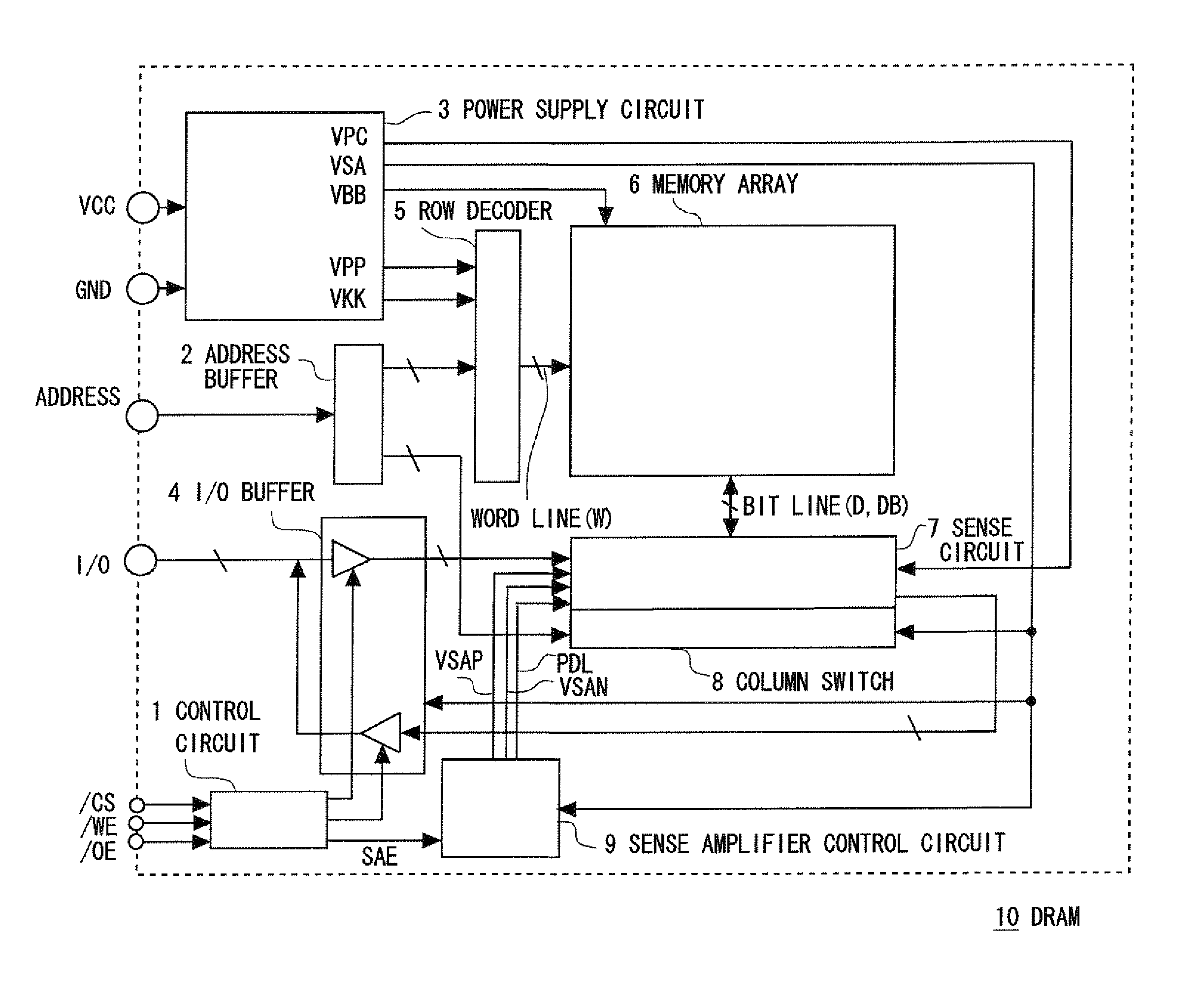
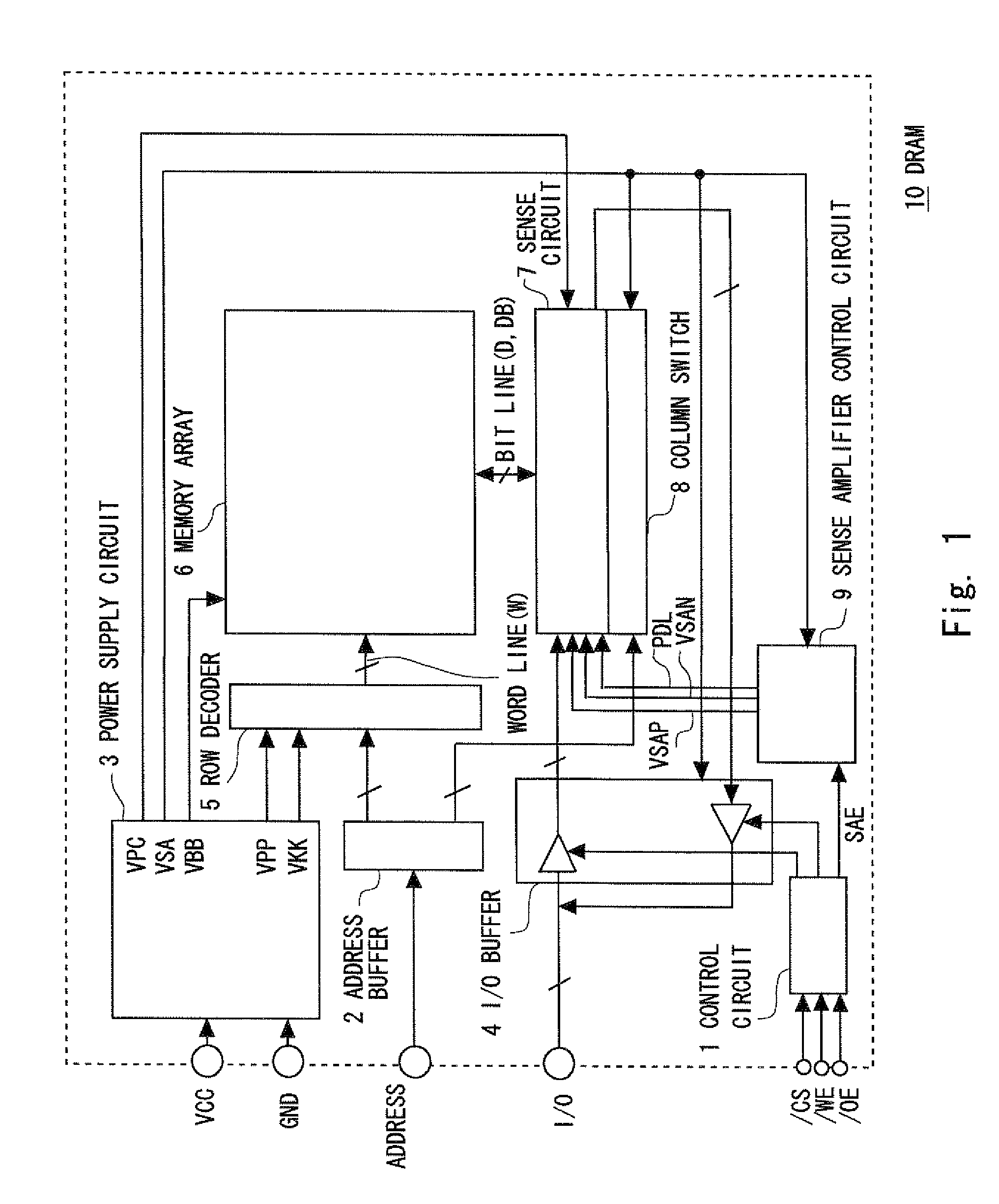
[0030]FIG. 1 is a diagram showing a whole semiconductor device according to the first embodiment of the present invention.

[0031]A DRAM 10 in FIG. 1 includes a power supply circuit 3 to which a power supply voltage VCC and a ground voltage GND are input. The power supply circuit 3 generates voltage VPP which is higher than the power supply voltage, or VSA, VPP, VKK which are lower than the ground voltage. Although the example is shown in which voltages such as VPP mentioned above are generated inside the DRAM, those voltages can be directly input from an external part of the DRAM.

[0032]VPP and VKK of those voltages are input to a row decoder 5 and are supplied to a gate of a DRAM cell of a memory array 6 through a word line W. VBB is supplied to the memory array 6 as a back gate voltage of the DRAM cell.

[0033]VSA is input to a sense amplifier control circuit 9, a column switch 8, and an I / O buffer 4 so as to control selection / non-selection of a column system of bit lines D and DB. VP...

second embodiment

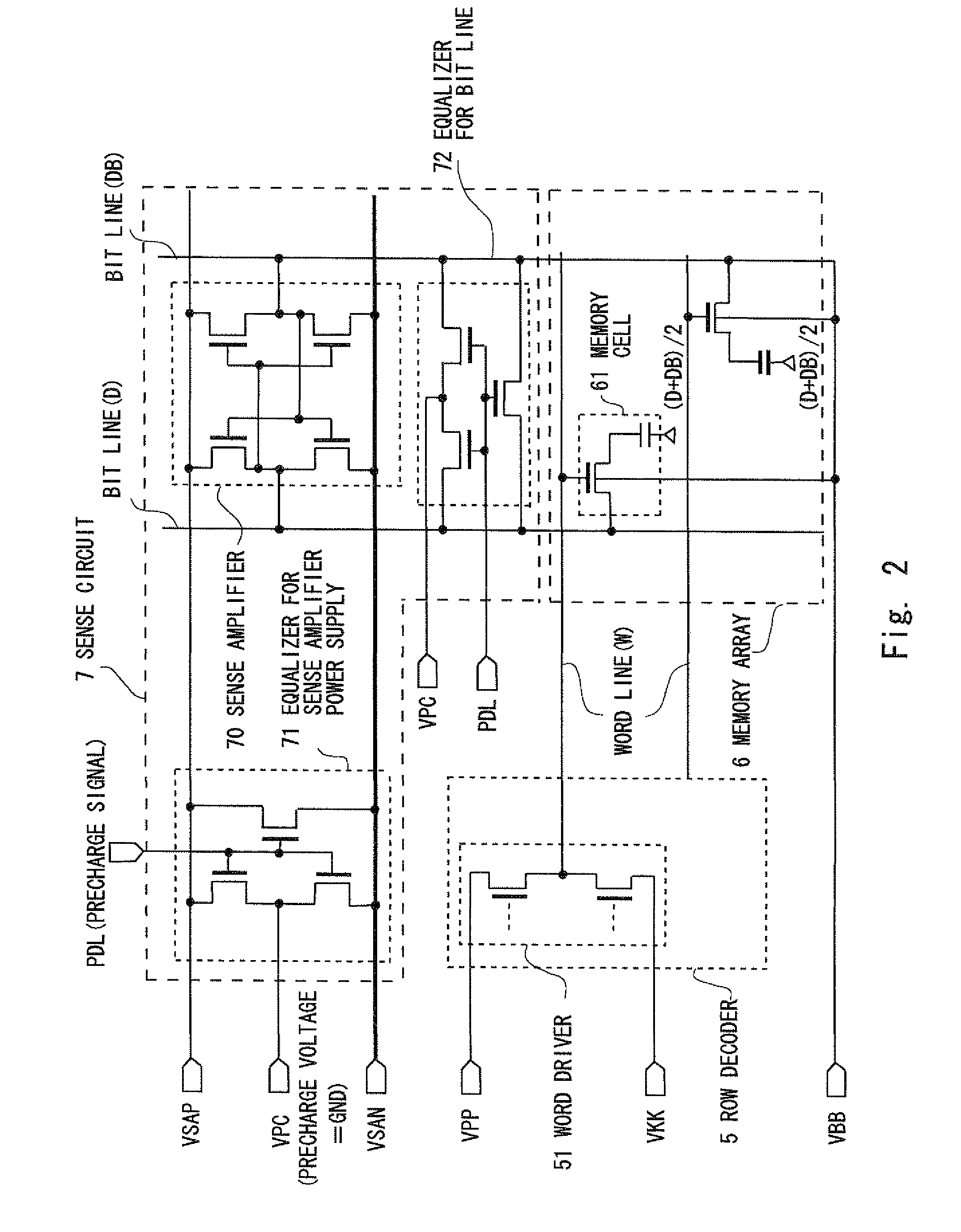
[0048]Now, an example of forming the DRAM cell transistor by the Pch transistor will be described. The whole image is the same as that in FIG. 1. As is the same as in FIG. 2, FIG. 5 shows a circuit diagram showing a part of the DRAM cell. FIG. 6 shows operational waveforms thereof. The parts different from those in the first embodiment will now be described with reference to FIGS. 5 and 6.

[0049]The configuration of the DRAM cell transistor in the second embodiment is almost the same as that in the first embodiment shown in FIG. 2. However, in the second embodiment, the memory cell 61 in FIG. 5 is the Pch transistor. The positive high voltage VPP is applied to the back gate voltage.

[0050]The precharge level which is the GND level in the first embodiment is set to the VCC level. Therefore, the equalizer for sense amplifier power supply 71 and the equalizer for bit line 72 are desirably formed by the Pch transistors.

[0051]The circuit operation of the present embodiment will be describe...


PUM


Abstract

According to a semiconductor device of the present invention, a differential potential between a sense amplification level and a precharge level of a sense amplifier is set to a power supply potential (VCC-GND) so as to improve resistance against degradation of hold characteristics. Further, low power consumption can be realized along with the improvement. Additionally, the precharge level is set to a power supply of GND or VCC so as to realize a stable supply of the precharge level. Further, a chip size can be reduced since a power supply circuit for precharge is not needed.

Description

BACKGROUND OF THE INVENTION[0001]1. Field of the Invention[0002]The present invention relates to a semiconductor device, and more specifically, to a sense operation of a DRAM.[0003]2. Description of Related Art[0004]In recent years, in a semiconductor device used in a communication device or a high-end computer, low power consumption or high-speed access has been required.[0005]Along with the low power consumption or the high-speed operation, highly enhanced performance has been required in the DRAM. More specifically, a power supply voltage input to the DRAM has been reducing.[0006]FIG. 7 shows waveforms showing an operation of a typical DRAM. Although the detailed description is omitted, sensing is performed by raising a sense amplifier activating signal SAE with a word line W being raised. A bit line pair D and DB, which has been precharged to an intermediate potential ½ VCC between a power supply voltage VCC and a ground voltage GND before starting the sensing, is set to a true ...

Claims


Application Information

Patent Timeline
Patent Type & Authority Applications(United States)
IPC IPC(8): G11C11/24G11C7/06G11C5/14
CPCG11C7/08G11C11/4094G11C11/4091
Inventor TAKAHASHI, HIROYUKI
Owner RENESAS ELECTRONICS CORP
Why Eureka
Try Eureka