
Polymer electrolyte membrane and membrane-electrode assembly for fuel cell and fuel cell system including same

a technology of electrolyte membrane and fuel cell, which is applied in the direction of fuel cell details, cell components, electrochemical generators, etc., can solve the problems of polymer electrolyte fuel cells, and achieve the effects of excellent ion conductivity and mechanical properties, and effective suppression of fuel cross-over

Inactive Publication Date: 2009-04-02
SAMSUNG SDI CO LTD
View PDF3 Cites 4 Cited by
  • Summary
  • Abstract
  • Description
  • Claims
  • Application Information

AI Technical Summary

Benefits of technology

[0012]It is another object of the present invention to provide a polymer electrolyte membrane having excellent proton conductivity and inhibition properties of fuel cross-over.
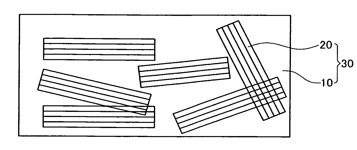
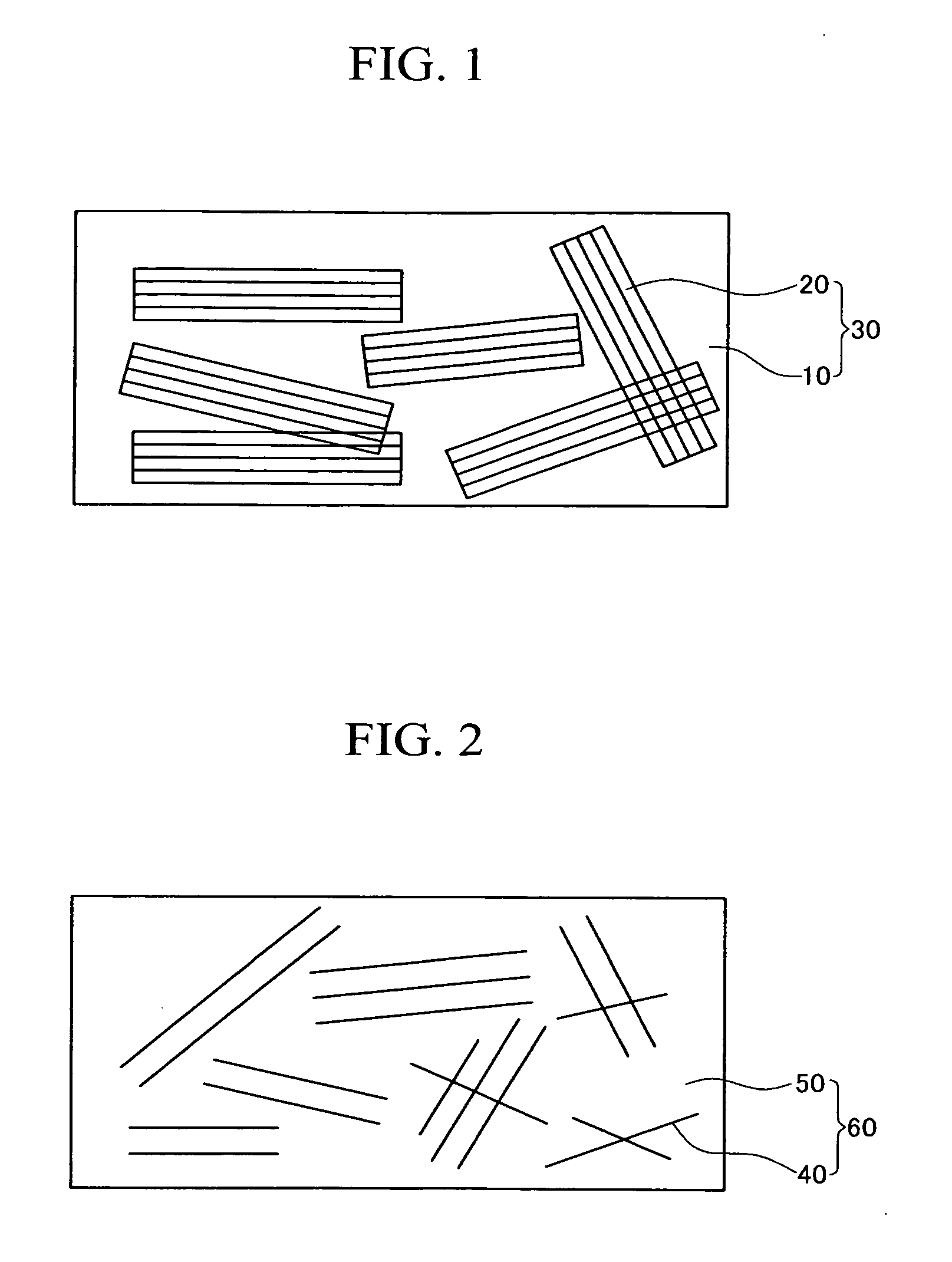
[0025]The polymer electrolyte membrane includes a nano-sized exfoliated mineral additive dispersed in the polymer electrolyte membrane, and thereby fuel cross-over could be effectively suppressed by a small amount of mineral additive while maintaining excellent ion conductivity and mechanical properties.

Problems solved by technology

The polymer electrolyte fuel cell has an advantage of a high energy density, but the polymer electrolyte fuel cell also has problems in the need to carefully handle hydrogen gas and the requirement of accessory facilities such as a fuel reforming processor for reforming methane or methanol, natural gas, and the like, in order to produce hydrogen as the fuel gas.

Method used


Image

  • Polymer electrolyte membrane and membrane-electrode assembly for fuel cell and fuel cell system including same
  • Polymer electrolyte membrane and membrane-electrode assembly for fuel cell and fuel cell system including same
  • Polymer electrolyte membrane and membrane-electrode assembly for fuel cell and fuel cell system including same

Examples


example 1

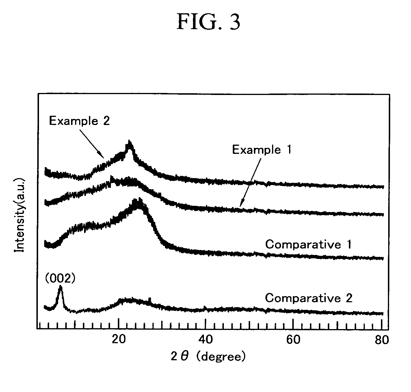
[0093]A powdery silicic acid-based clay material of silicon oxide mixed with sodium oxide (mole ratio of SiO2 / Na2O of 2.07) was fired at 600° C. to synthesize Na2Si2O5. The synthesized Na2Si2O5 was mixed with water in a weight ratio of 20:80 to synthesize a kanemite using a mechanical agitator. The provided kanemite was added into 1-butanol at a weight ratio of 20:80 to provide a mineral additive solution, and it was agitated with an agitator at room temperature for 24 hours.

[0094]The agitated mineral additive solution was allowed to stand for 7 days to precipitate the powders and to separate the supernatant, and the mineral additive solution was then dried under the room pressure condition to provide a single-layered kanemite in which a plurality of layers were exfoliated.

[0095]The aspect ratio of the kanemite was 600 to 800.

[0096]A commercially available perfluorosulfonate resin solution (Solution Technology, 5 wt % Nafion / H2O / 2-Propanol, EW 1100), dissolved in water and 2-propano...

example 2

[0100]A polymer electrolyte membrane was provided in accordance with the same procedure as in Example 1, except that the mineral additive was present at 3 parts by weight based on 100 parts by weight of the cation exchange resin.

example 3

[0101]A polymer electrolyte membrane was provided in accordance with the same procedure as in Example 1, except that a commercially available makatite was used.

[0102]The provided polymer electrolyte membrane had an overall thickness of 50 μm, and the mineral additive was exfoliated in a nano-size and was dispersed in a single-layered structure in a polymer electrolyte membrane. The ratio of the mineral additives to the cation exchange resin in the polymer electrolyte membrane was 1 part by weight based on 100 parts by weight of the cation exchange resin.


PUM

PropertyMeasurementUnit
Percent by massaaaaaaaaaa

Abstract

A polymer electrolyte membrane is provided with a cation exchange resin and a mineral additive including an exfoliated layered silicic acid-based clay. The polymer electrolyte membrane includes the nano-sized exfoliated mineral additive dispersed in the polymer electrolyte membrane, and thereby fuel cross-over can be effectively suppressed by the small amount of mineral additive while maintaining excellent ion conductivity and mechanical properties.

Description

CLAIM OF PRIORITY[0001]This application makes reference to, incorporates the same herein, and claims all benefits accruing under 35 U.S.C. §119 from an application earlier filed in the Korean Intellectual Property Office on Sep. 28, 2007 and there duly assigned Serial No. 10-2007-0097912.BACKGROUND OF THE INVENTION[0002]1. Field of the Invention[0003]The present invention relates to a polymer electrolyte membrane for a fuel cell, and a membrane-electrode assembly and a fuel cell system including the polymer electrolyte membrane. More particularly, the present invention relates to a polymer electrolyte membrane for inhibiting fuel cross-over, and a membrane-electrode assembly and a fuel cell system including the polymer electrolyte membrane.[0004]2. Description of the Related Art[0005]A fuel cell is a power generation system for producing electrical energy through an electrochemical redox reaction of an oxidant and hydrogen in a hydrocarbon-based material such as methanol, ethanol, o...

Claims


Application Information

Patent Timeline
IPC IPC(8): H01M8/10
CPCH01M8/04261Y02E60/522H01M8/1011H01M8/1016H01M8/1023H01M8/1025H01M8/1027H01M8/103H01M8/1032H01M8/1039H01M8/1048H01M2300/0082H01M2300/0088Y02E60/523H01M8/1009H01M8/04197Y02E60/50H01M8/10H01M8/02H01M4/86B82Y30/00
Inventor JANG, MOON-YUP
Owner SAMSUNG SDI CO LTD
Learn More