Optical pickup, optical disk device, computer and optical disk recorder

a technology of optical disk and pickup, which is applied in the field of optical disk device, computer and optical disk recorder, can solve the problems of deteriorating the quality of signals, high production cost, and complicated manufacturing process of wavelength selective apertures that employ multi-layer optical films, and achieves low cost, mass production, and sufficient effect of aperture restriction

Inactive Publication Date: 2009-04-16
PANASONIC CORP
View PDF4 Cites 5 Cited by
  • Summary
  • Abstract
  • Description
  • Claims
  • Application Information

AI Technical Summary

Benefits of technology

[0021]The present invention provides the optical pickup that records/reproduces information on/from a BD, a DVD and a CD with a single objective lens, having such a constitution as sufficient effect of aperture restriction is achieved for the light of different wavelengths according to the different types of optical disks by means of the diffraction aperture element without using an optical filter b

Problems solved by technology

The wavelength selective aperture that employs the multi-layer optical film requires a complicated manufacturing process as described above and high production cost, since the steps of vapor deposition of the metal film, masking, vapor deposition of the multi-layer optical film and lifting off are repeated three times.
This means that, although the aperture can be restricted for the outwar

Method used


Image

  • Optical pickup, optical disk device, computer and optical disk recorder
  • Optical pickup, optical disk device, computer and optical disk recorder
  • Optical pickup, optical disk device, computer and optical disk recorder

Examples


first embodiment

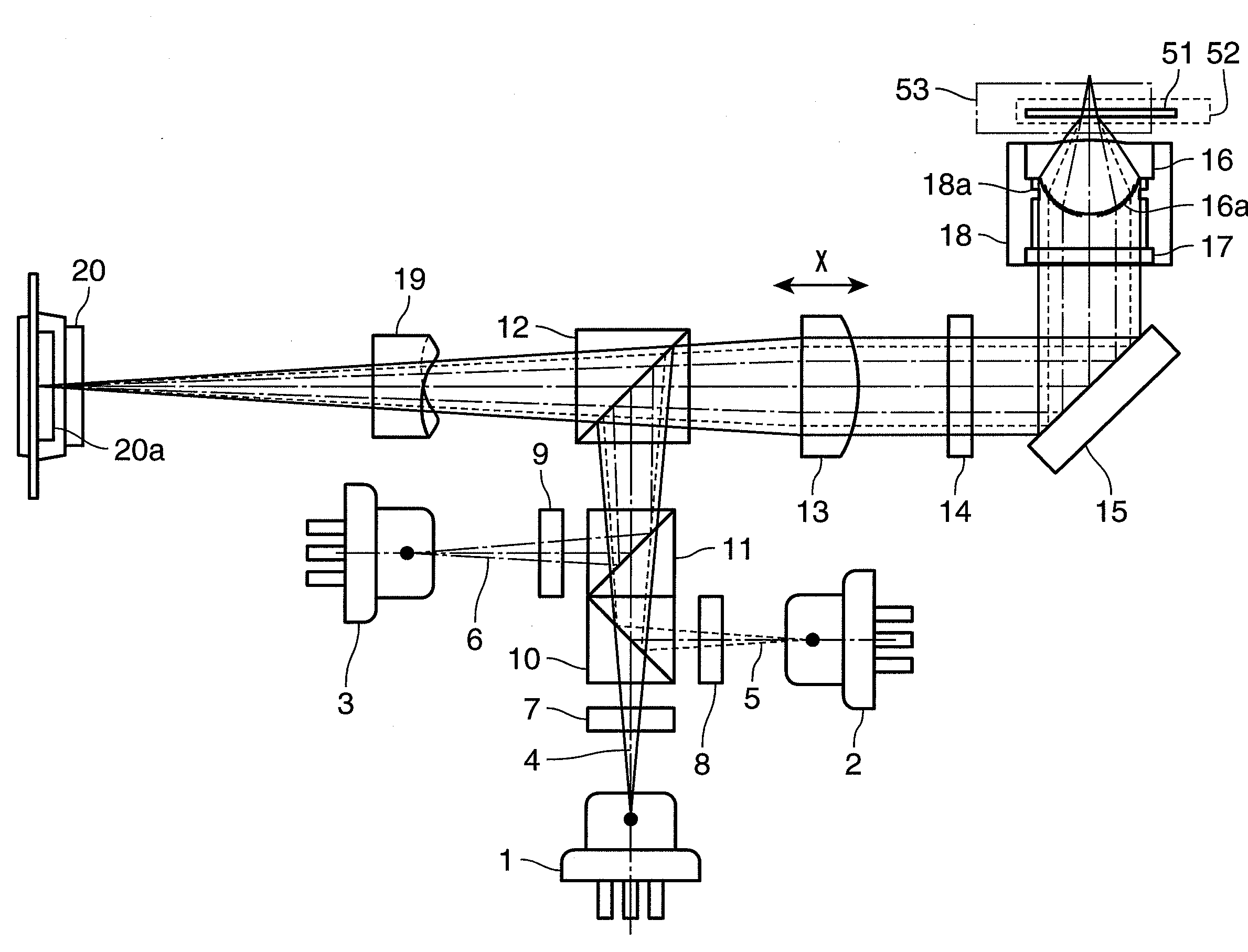
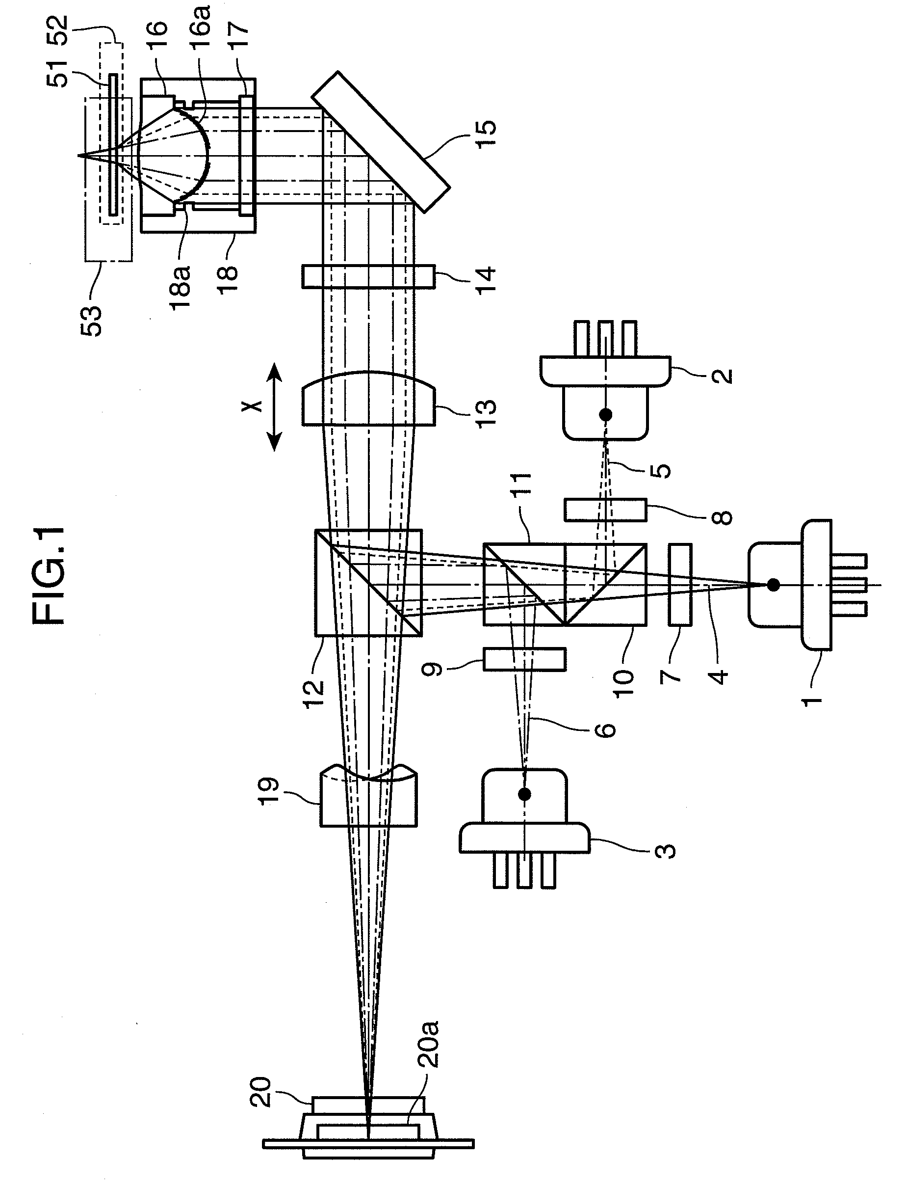
[0044]FIG. 1 shows the constitution of an optical pickup according to the first embodiment of the present invention. In FIG. 1, the optical pickup comprises a blue laser 1, a red laser 2, an infrared laser 3, diffraction gratings 7, 8, 9, dichroic prisms 10, 11, a beam splitter 12, a collimator lens 13, a wavelength plate 14, a mirror 15, an objective lens 16, a diffraction aperture element 17, a lens barrel 18, a detector lens 19 and a photodetector 20.

[0045]The blue laser 1 emits light of wavelength λ1 (approximately 405 nm). The red laser 2 emits light of wavelength λ2 (approximately 655 nm). The infrared laser 3 emits light of wavelength λ3 (approximately 780 nm). The optical disk 51 is an optical information medium such as a BD optical disk, having a protective layer of thickness t1 being about 0.075 mm or about 0.1 mm, of which information is recorded / reproduced by means of a light beam of wavelength λ1. The optical disk 52 is an optical information medium such as a DVD optica...

second embodiment 2

[0069]FIG. 11 is a sectional view of a diffraction aperture element according to the second embodiment of the present invention, and shows a portion from the optical axis to one end in an enlarged view. In the diffraction aperture element 21 shown in FIG. 11, diffraction regions are provided on two surfaces 211, 212. One surface 211 has a plain region 21a in a circle of radius R1, and a first diffraction region 21b that has diffraction grating with a depth of h1 is formed outside the circle of radius R1, and the other surface 212 has a plain region 21c in a circle of radius R2 and a second diffraction region 21d that has diffraction grating with a depth of h2 formed outside the circle of radius R2. More specifically, the surface 211 has the first diffraction region 21b having an annular configuration of inner radius R1 with respect to the optical axis as a center with the diffraction grating formed with a depth h1. The first diffraction region 21b has an outer radius R2 (R2>R1) or l...

third embodiment

[0081]FIG. 14 shows the schematic constitution of an optical disk device that employs the optical pickup of the first embodiment or the second embodiment. The optical disk device 107 comprises a drive device 101, an optical head 102, an electrical circuit 103, a motor 104 and a turntable 105. In FIG. 14, an optical disk 100 is placed on the turntable 105, and is driven by the motor 104 to rotate. The optical pickup 102 according to the first embodiment or the second embodiment is transferred by the drive device 101 to a track of the optical disk 100 where desired information is recorded.

[0082]The optical pickup 102 sends a focusing error signal or a tracking error signal according to the positional relationship with the optical disk 100 to the electrical circuit 103. In accordance to the signal, the electrical circuit 103 sends a signal to the optical pickup 102 for driving the objective lens. The optical pickup 102 uses this signal to control focusing and tracking of the optical di...


PUM


Abstract

A diffraction grating is constituted such that directions of diffraction are disposed asymmetrically with respect to the optical axis, by causing light subjected to aperture restriction to have a difference of one half wavelength in the optical path length by making use of the fact that the difference in the optical path length experienced by the light passing through a diffraction element varies depending on the wavelength. With this constitution of the diffraction grating, aperture restriction is applied to both the light focused on an optical disk and the light reflected from the optical disk, thereby achieving an optical pickup that is capable of recording/reproducing information on/from optical disks of different types by using a single objective lens. The optical pickup prevents unnecessary light from entering a photodetector and enables the production of diffraction elements at a low cost.

Description

TECHNICAL FIELD[0001]The present invention relates to an optical pickup that records information on an optical information medium such as an optical disk, reproduces or deletes information therefrom, an optical disk device that uses the optical pickup, a personal computer where the device is applied, and a system such as optical disk recorder that records video and audio signals.BACKGROUND ART[0002]With the compact disk (hereinafter referred to as CD), that may be called the first generation optical disk, information is recorded on or reproduced from (hereinafter expressed as record / reproduce) an optical disk having a protective layer 1.2 mm in thickness by using an objective lens with a numerical aperture from 0.45 to 0.5 and infrared rays of wavelength 780 nm. In this specification, the term protective layer means a transparent medium disposed between a surface whereon a light beam incident on the optical disk strikes and an information recording surface. In a digital versatile di...

Claims


Application Information

Patent Timeline
IPC IPC(8): G11B7/00G11B7/125G11B7/135
CPCG11B7/1275G11B7/1353G11B2007/0006G11B7/139G11B7/1374
Inventor MIZUNO, SADAO
Owner PANASONIC CORP
Why Eureka
Try Eureka