In addition, during treatment, there was limited, if any,
verification of the orientation of the eye relative to the pre-operative CT scan or
verification of maintenance of eye orientation during treatment.
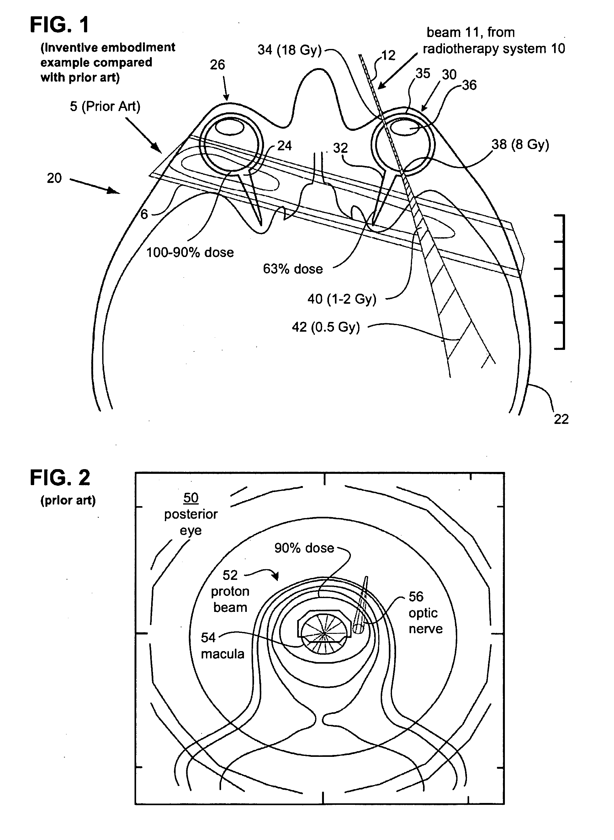
Due the penetrating nature of the MeV
radiation and the beam width, among other things, prior art treatment beam 6 results in substantial
irradiation of the non-targeted structures.
In addition, these prior art attempt at applying radiation to the macula did not consider eye movements or
eye position.
Such
fractionation and minimalist dosing and planning schemes likely lead to the lack of
efficacy in those studies.
Another significant limitation of the treatments in prior art external beam trials, there was no accounting for
eye movement and position during the treatment.
However, the
eye movement and the center of rotation vary from patient to patient, and it is difficult to know the exact
dose applied to the macula.
In addition, eye location and movement were not controlled in this study.
Such complications likely negated any benefit of the therapy.
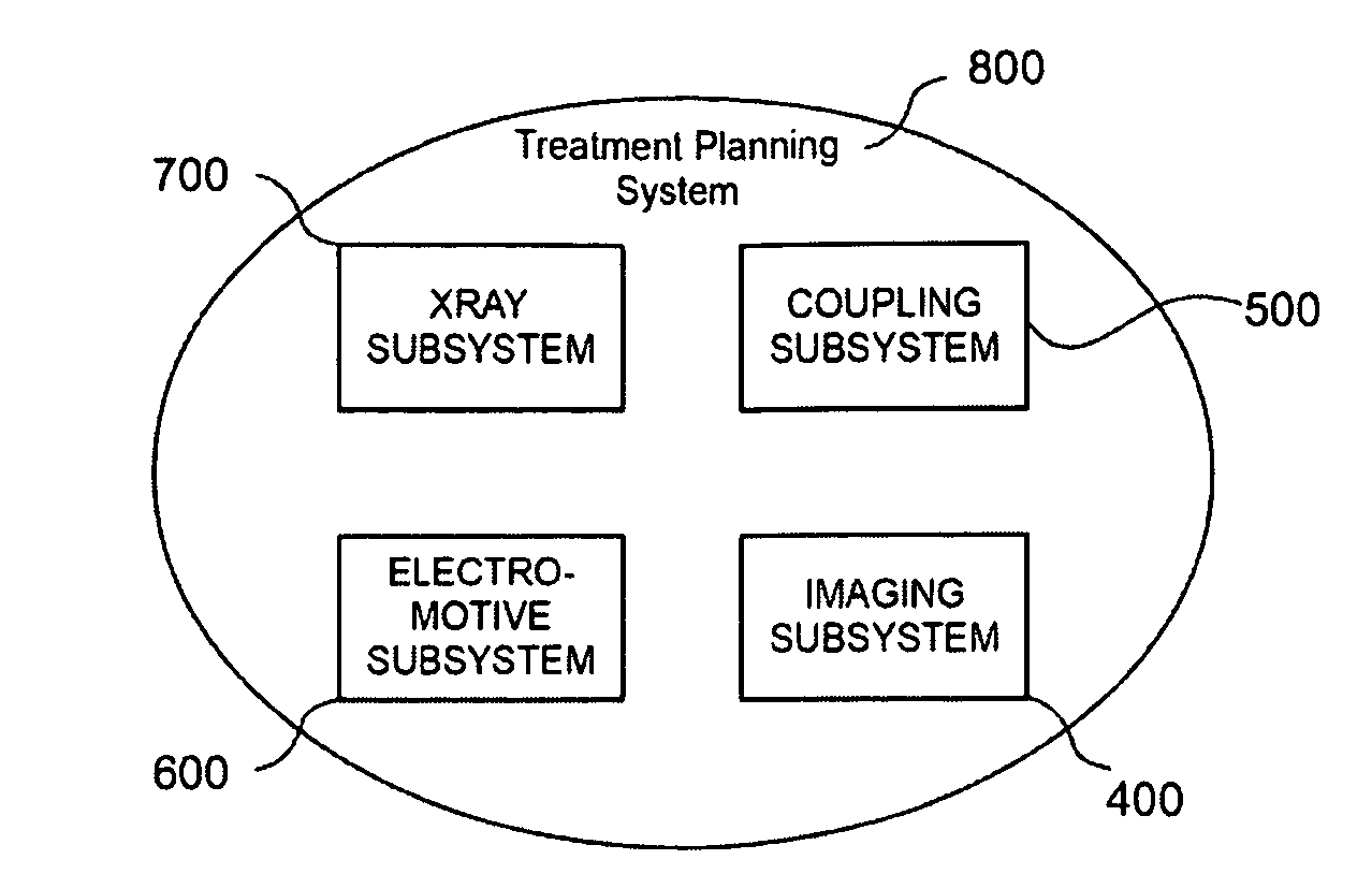
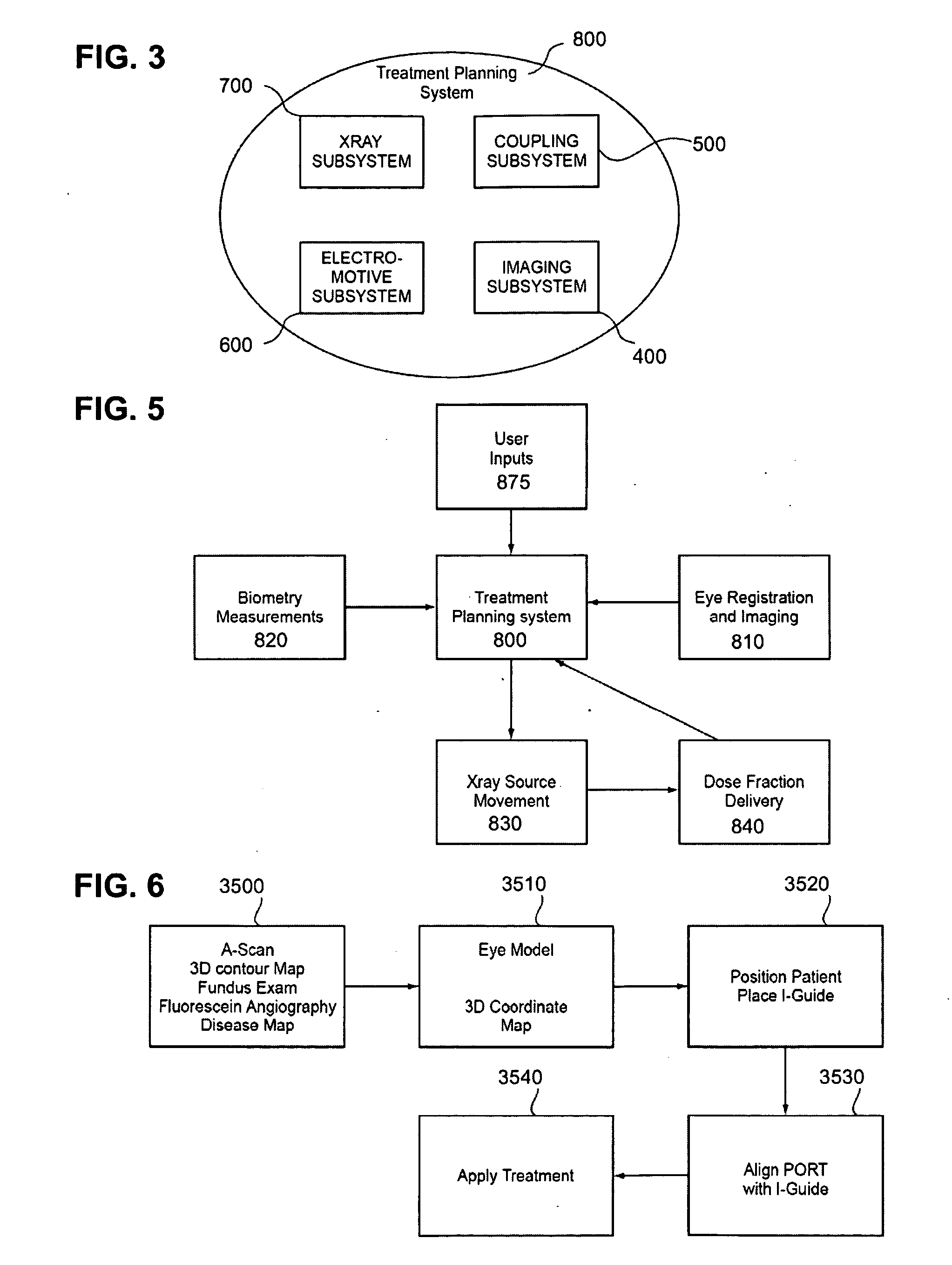
Although relatively sophisticated, the
system 800 may be limited to the ophthalmic region and therefore takes
advantage of specific
imaging equipment only available for the eye.
Adjustment of the power on the power supply will result in a decrease in the peak
voltage of x-rays, limiting the amount of higher energy photons.
Note that further increases in polar angle may present inconvenience or discomfort with respect to the range of
eyelid retraction, or by interference with the beam by tissues adjacent the eye.
It has been found that the average shift values shown lead to surprisingly small errors in the
population studied, a
maximum error of 0.20 mm in the horizontal direction and 0.08 mm in the vertical direction.
The heat generated by the
anode is the major
limiting factor in the ultimate flux which can be achieved by the x-
ray source.
However, its
dose uniformity is significantly reduced within the macula target.
On the other hand, a real or at least conceptual
hazard of high degree-of-freedom
robotic systems employing energy beam treatment, is the large possible range of beam paths (e.g., upon a
control system failure), and associated risk issues, regulatory complexity, and high end-user installation and site modification costs.
However, the da Vinci is not autonomous and requires an expert surgeon to move its arms.
However, the linear accelerator which moves around the patient is over 1
ton in weight and cannot move close enough to the patient to deliver beams of X-
ray to the eye.
Furthermore, the
system does not include an eye stabilization system to allow for alignment relative to the eye.
In addition, a real or at least conceptual
hazard of high degree-of-freedom
robotic systems employing energy beam treatment, is the large possible range of beam paths (e.g., upon a
control system failure), and associated risk issues, regulatory complexity, and high end-user installation and site modification costs.
Because each
treatment dose is relatively short and applied over a small distance, the
robot can sacrifice speed and travel distance for smaller size.
In one preferred embodiment, negative pressure applied to the eye, for example, a negative pressure of 20-50 mm Hg, is effective to stabilize the position of the eye on the device, that is, substantially prevent movement of the eye with respect to the device, but by itself is not sufficient to hold the eye-contact device on the eye.
1. Exceeding
retinal motion threshold. As described herein and in the incorporated applications, the
eye tracking data may be employed to determine one or more discrepancy or error values based on a target movement or motion-related
dose distribution, such as a maximum target displacement, a cumulative
retina displacement vector, a
dose distribution indicator, or the like. The error value may in turn be compared on a real-time basis with a gating threshold value to trigger a gating event. Optionally,
eye tracking algorithms may be used to track motion or dose relative to non-target structures, such as the limbus, lens of the eye, optic nerve and the like, with respective gating thresholds.(a) In a one motion-threshold example embodiment for a
retinal target region, the error value may be the current scalar magnitude of a summation vector representing cumulative
retina target motion derived on a time increment basis (e.g., camera frame-by-
frame rate or a selected sub-sampling rate) from
eye tracking data. For example the vector inputs may include components in the X and Y directions of the retinal target plane, indicating the X and Y deviations at each measured time of the beam center from the target center. The vector summation accumulates these components as directional vector quantities, the scalar magnitude representing the radial distance from the target center of the summation vector (square root of the sum of the squares of the components). Such a summation vector magnitude represents the time-weighted cumulative
displacement error in the position of the beam-spot center from the planned retina target center point. The vector may be linear, or alternatively have quadratic or other non-
linear distance weighting so as to de-emphasize small fluctuations in position (e.g.,
jitter or vibration) relative to larger, continuous displacements. Upon reaching a pre-selected scalar magnitude threshold, gating (interruption) of the X-
ray source can then be triggered.(b) A calibrated “motion-free”
dose distribution may be determined experimentally and / or computationally (e.g., Monte Carlo
simulation and / or radiographic beam-spot measurements) representing the dose distribution either at the target region (e.g., macula surface) or at any other tissue location within or adjacent to the
radiation beam path. From the calibrated dose distribution, an equivalent time-increment dose distribution may be determined for a desired time increment (e.g. video
frame rate).
Retina or other tissue motion can then be derived from eye
tracking data as described herein, and such motion data can be used to modulated with time-increment dose distribution so as to yield a contribution for each time increment to a
cumulative dose distribution accounting for measure eye motion. Such motion-modulated dose distribution may be used to validate or determine a motion-threshold value as in 1(a) above by determining the dose distribution at the gating trigger point. Alternatively the motion-modulated dose distribution may be used to evaluate the adequacy of
treatment dose level within the planned target region 318.(c) Alternatively, the motion-modulated dose distribution of 1(b) may be determined on a real-time basis at any desired
anatomical location within the distribution, and such dose may compared to a dose-threshold be used to trigger gating. For example, a maximum
cumulative dose at the edge of the
optic disk may be used to trigger gating.(d) Alternatively or additionally, the real-time determined
cumulative dose distribution of 1(c) may be evaluated within the planned target region, and may be used to trigger termination of treatment at a desired target treatment profile, including motion-related eye-dose distribution effects. Examples include triggering gating-termination upon (i) reaching a selected maximum
treatment dose level at highest-dose point in a defined target region; (ii) reaching a selected minimum treatment
dose level at the lowest dose point within a defined target region; (iii) reaching a selected average dose within a defined target region; (iv) a combination of these (e.g., reaching at least a selected average dose after achieving a selected low-point minimum); or the like.
2.
System-level functional diagnostics. Gating may be triggered by error or failure conditions such as loss of eye tracking by the system, loss of limbus tracking, or other system-based failure deemed justification for interruption of radiation treatment, e.g., due to electronic conditions, camera conditions, lighting conditions, inadvertent blocking or interference with imaging, and the like. Alternatively or additionally, processor 501 may determine and monitor a selected number of different diagnostic conditions which can be used to trigger gating, such as X-ray tube parameters, lighting parameters,
laser pointer 1410 position tracked relative to the limbus (limbus clearance), and the like.
3. Patient-level interlocks. Alternatively or additionally, processor 501 may determine and an monitor a selected number of patient-based
interlock or diagnostic conditions which can be used to trigger gating.(a) These may include specific patient
interlock sensor signals, such as indicating disconnect of
head restraint fasteners, disconnect of eye-guide lens mounting (see step 2534); patient hand grip 163 contact sensors (See FIG. 33A), and the like.(b) The patient-based condition may also be determined by
image processing / recognition from one or more cameras or other
remote sensors. For example, the relative positions of eye-guide 110 and limbus 26 may be monitored continuously during treatment via camera-based eye tracking and compared against a selected threshold indicating disconnect or decoupling of the eye-guide lens 120 from the patients eye (such as by sliding of the lens over the
cornea). An error condition may be determined so as to trigger gating of radiation.
(c) In a further example, transitory “blinking” compensation gating embodiments are described in co-invented Application No. 61 / 093,092 filed Aug. 29, 2008, which is incorporated by reference. The transitory gating embodiments compensate for sudden, brief, large magnitude, generally vertical displacements which result from involuntary blinking or spasmodic movements of the eye, typically followed by a quick return to a generally well-aligned eye position. These eye movements may be rapidly detected by image-based eye tracking so as to trigger a rapid-response radiation gating. Treatment radiation may be automatically resumed, either after a
fixed time delay or an automatic realignment confirmation. This “blinking” type gating may be used independently or in combination with retinal motion threshold gating described in Subsection 1 above.
However, the eye motion does result in a
relative motion of the beam spot on the retina due to the angled alignment of the beam with the retina.
Vascular damaging agents (VDAs) cause a rapid shutdown of established vasculature, leading to secondary tissue death.

