Method of forming a bottle-shaped trench by ion implantation

Inactive Publication Date: 2009-07-02
GLOBALFOUNDRIES INC
View PDF31 Cites 169 Cited by
  • Summary
  • Abstract
  • Description
  • Claims
  • Application Information

AI Technical Summary

Benefits of technology

[0007]The present invention provides a method for forming a bottle shaped tre

Problems solved by technology

The aforementioned conventional methods of fabricating a bottle shaped trench have the disadvantage in that forming a protection, sacrificial or disposable layer, or providing a filler material increases the complexity of the fabrication proc

Method used


Image

  • Method of forming a bottle-shaped trench by ion implantation
  • Method of forming a bottle-shaped trench by ion implantation
  • Method of forming a bottle-shaped trench by ion implantation

Examples


first embodiment

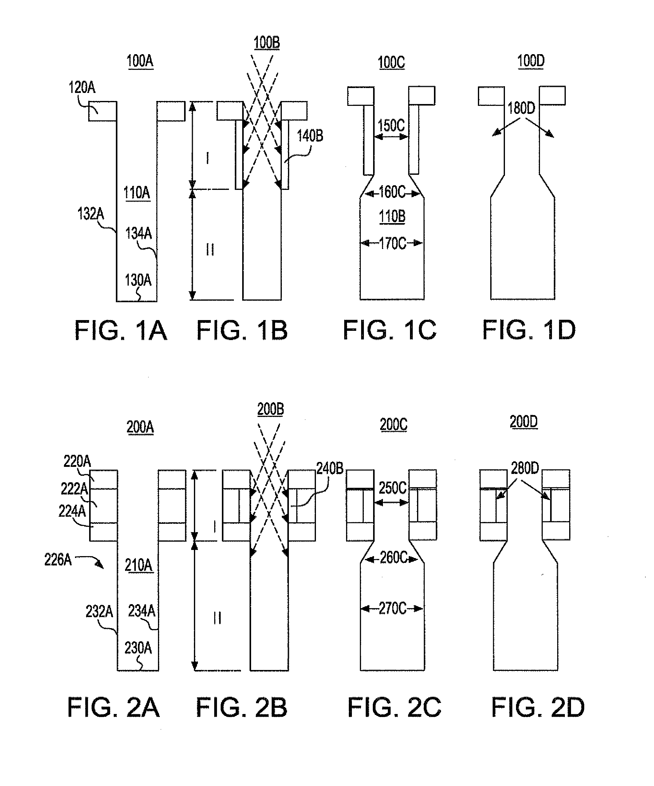
[0036]The implanted ions in accordance with the present invention can be any ion that is capable of rendering the semiconductor substrate amorphous. Examples of such amorphizing ions include, but are not limited to, argon, krypton, neon, helium, boron, indium, thallium, carbon, silicon, germanium, nitrogen, phosphorus, arsenic, sulfur, iodine, oxygen, boron fluoride, or any combination of these ions. To render the substrate abutting the upper portion of the trench amorphous in accordance with one possible embodiment of the present invention requires ion energy levels, depending on the implanted ions and the implantation angle, within a range from about 2 to about 800 keV. A preferred range is from about 10 to about 200 keV and a most preferred range is from about 30 to about 60 keV. The dose of the amorphizing ions being implanted may vary depending on the type of amorphized ion being implanted. Typically, the dose of the implanted amorphizing ion is from about 1×10¹⁷ to about 1×10²...

third embodiment

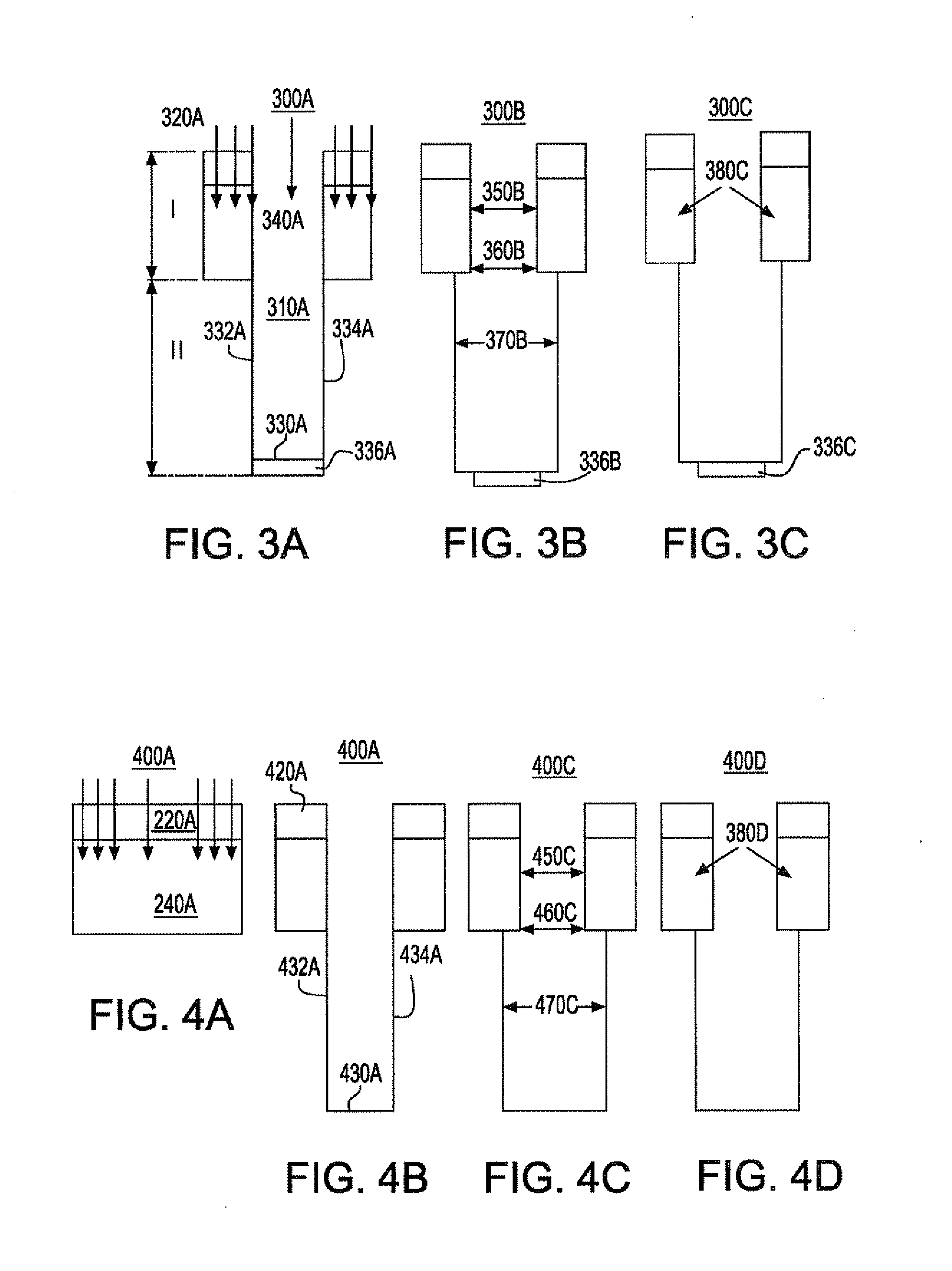
[0046]An optional thermal anneal step may be employed with respect to the third embodiment as discussed above. Particularly, an optional thermal anneal step can be performed to the upper portion I of the trench to re-crystallize that portion into a single crystal as shown in FIG. 3C. Again, the amorphous base 336B may optionally be removed and discarded by an etching method, as discussed above. In FIG. 3C, reference numeral 380D denotes the re-crystallized region and reference numeral 336C denotes a re-crystallized base.

[0047]In accordance with a fourth embodiment of the present invention, the above steps, described in reference to the first embodiment are again employed in forming a bottle shaped trench in a semiconductor substrate by ion implantation wherein trench capacitance is enhanced. However, as shown in FIG. 4A-4C, the sequence of the steps are rearranged. The beam of ions to be implanted as depicted by the arrows in FIG. 4A are perpendicular to the surface area of the subs...


PUM


Abstract

Disclosed is a method of forming a bottle shaped trench in a substrate which includes forming at least one trench having an upper portion and a lower portion into a semiconductor substrate, the at least one trench having vertical sidewalls that extend to a common bottom wall; implanting ions into the semiconductor substrate abutting the upper portion of the at least one trench to form an amorphous region in the semiconductor substrate abutting the upper portion of the at least one trench; and etching the lower portion of the at least one trench selective to the amorphous region to provide an elongated bottom portion which extends laterally beyond the upper portion.

Description

RELATED APPLICATION[0001]This application is a continuation of U.S. Ser. No. 11 / 965,399, filed Dec. 27, 2007FIELD OF THE INVENTION[0002]The present invention generally relates to the fabrication of semiconductor devices, and more particularly, to a method of forming a bottle shaped trench in a substrate by ion implantation wherein trench capacitance is enhanced.DESCRIPTION OF THE PRIOR ART[0003]A bottle shaped trench has been proposed as a method of increasing the storage capacitance in a semiconductor device. As used herein, the term “bottle shaped trench” denotes a trench having an upper and lower portion wherein the lower portion is elongated relative to the upper portion. Bottled shaped trenches are typically used to form a trench capacitor in an integrated circuit (IC). Some examples of ICs containing trench capacitors located in a bottle shaped trench include, for example, a random access memory (RAM), a dynamic random access memory (DRAM), a synchronous DRAM (SDRAM), and a re...

Claims


Application Information

Patent Timeline
IPC IPC(8): H01L21/3065
CPCH01L21/3065H01L21/0337
Inventor CHENG, KANGGUOFALTERMEIER, JOHNATHAN E.RADENS, CARL
Owner GLOBALFOUNDRIES INC
Why Eureka
Try Eureka