Gas field ion source, charged particle microscope, and apparatus

Active Publication Date: 2009-07-09
HITACHI HIGH-TECH CORP
View PDF27 Cites 54 Cited by
  • Summary
  • Abstract
  • Description
  • Claims
  • Application Information

AI Technical Summary

Benefits of technology

[0023]In a gas field ion source, the fourth challenge of the present invention that is how to reduce the mechanical vibration of an emitter tip can be solved by using a solid state coolant that is in the state of a gas at ordinary temperature under atmospheric pressure as the coolant in a system to cool at least one of the electrodes of an electrostatic lens. Otherwise the fourth challenge can be solved by making an emitter tip retention mechanism movable from the gas molecule ionization chamber and mechanically connecting the emitter tip retention mechanism to a cooling system with a flexible member.
[0024]The present invention makes it possible to provide a gas field ion source that can: simultaneously increase a conductance during rough vacuuming and reduce an extraction electrode aperture diameter from the viewpoint of the increase of ion current; and obtain an ion beam

Problems solved by technology

Further, another problem has been that, if the number of gas molecules increases at the exterior of the gas molecule ionization chamber, the gas molecules having collided with a radiation shield or the vacuum chamber wall having a higher temperature than the gas molecule ionization chamber collide with the gas molecule ionization chamber and thereby the temperature of the gas molecule ionization chamber rises and the ion current lowers.
Further, another problem has been that, if an emitter tip absorbs impurity molecules in a gas field ion source, ions are emitted fr

Method used


Image

  • Gas field ion source, charged particle microscope, and apparatus
  • Gas field ion source, charged particle microscope, and apparatus
  • Gas field ion source, charged particle microscope, and apparatus

Examples


first embodiment

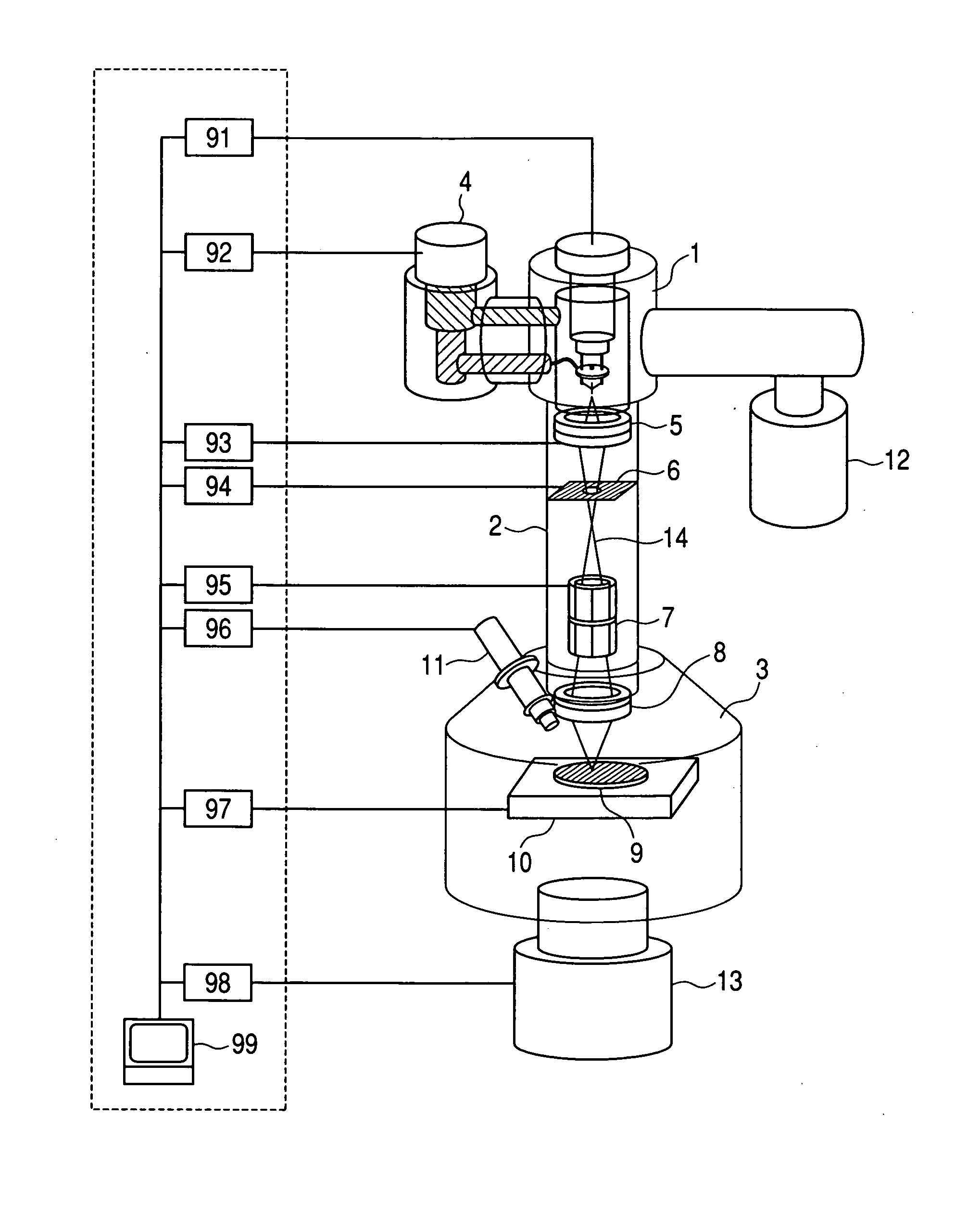
[0046]A general configuration diagram of an ion beam microscope according to the first embodiment is shown in FIG. 1. The present apparatus comprises a gas field ion source 1, an ion beam irradiation column 2, a vacuum sample chamber 3, and others. A refrigerator 4 is connected to the gas field ion source 1. An electrostatic type condenser lens 5, a beam limiting aperture 6, a beam scanning electrode 7, an electrostatic type object lens 8 and others are stored in the ion beam irradiation column 2. A sample stage 10 on which a sample 9 is mounted, a secondary particle detector 11, and others are stored in the vacuum sample chamber 3. Further, an ion source vacuuming pump 12 and a sample chamber vacuuming pump 13 are attached. Here, it goes without saying that the interior of the ion beam irradiation column 2 is also maintained in the state of vacuum.

[0047]As units (or referred to as sections) to control the present microscope, a gas field ion source controller 91, a refrigerator cont...

second embodiment

[0076]Although a pulse tube refrigerator having relatively low vibration is used in the first embodiment, it sometimes happens that the pulse tube refrigerator is not satisfactory for minimizing the diameter of an ion beam. In the second embodiment, a refrigerator combining a GM type refrigerator and a helium gas pot is used in place of the pulse tube refrigerator.

[0077]The GM type refrigerator has a first cooling stage where temperature lowers to about 50 K and a second cooling stage where temperature can be lowered to 4 K. Those cooling stages are covered with a sealed type pot. Then the pot is filled with helium gas. That is, the GM type refrigerator cools helium gas and the helium gas cools the outer wall of the pot. By the cooling system, the tip of the pot is cooled to about 6 K and the vicinity of the first cooling stage is cooled to about 70 K. In the present refrigeration system, even though the GM type refrigerator vibrates, the mechanical vibration is transferred in an at...

third embodiment

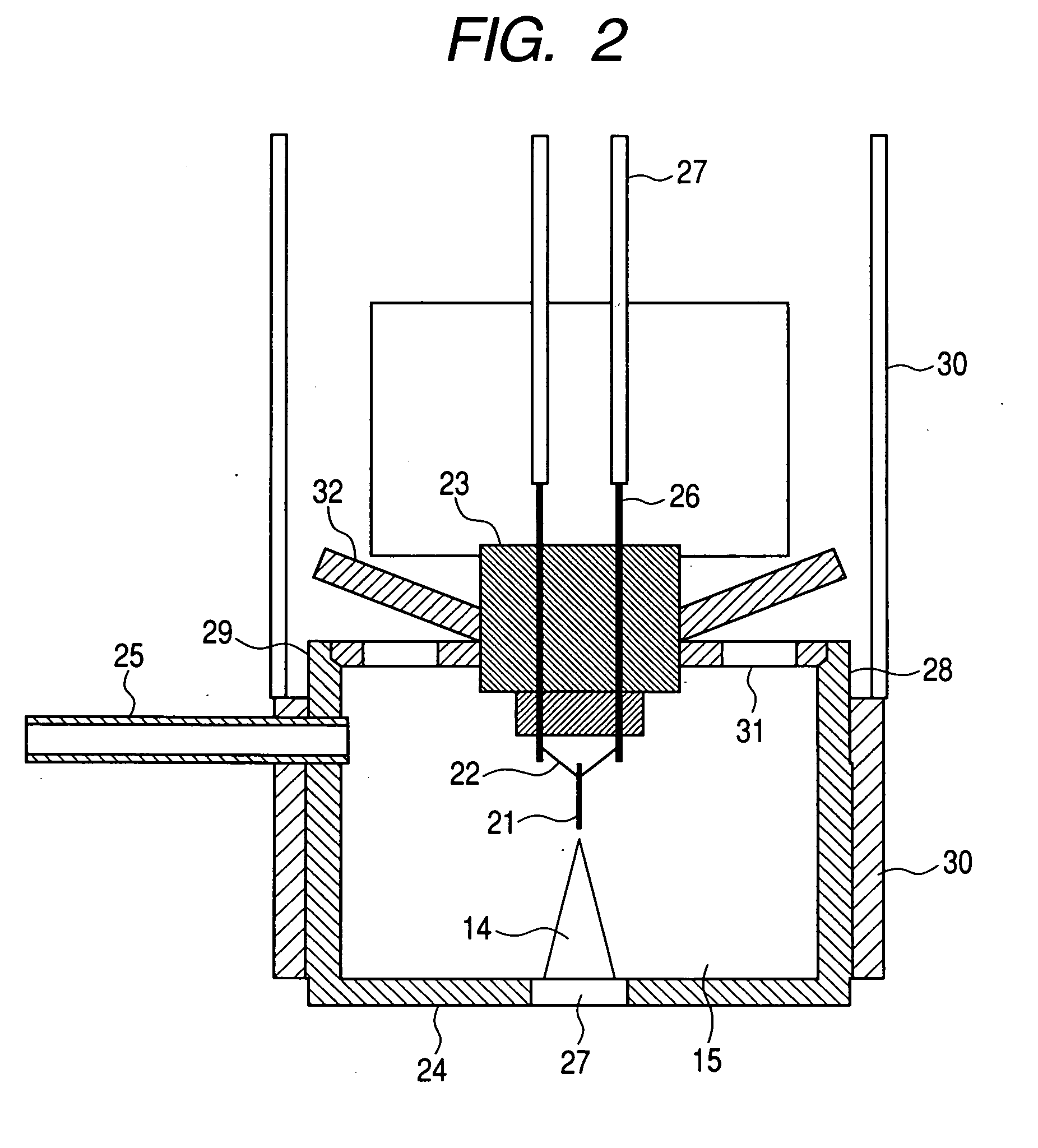
[0079]A refrigerator is used in the first and second embodiments. However, a refrigerator essentially yields mechanical vibration and is likely to transfer the vibration to an emitter tip. In a charged particle microscope, the vibration of the emitter tip causes an irradiation beam spot on a sample to vibrate and the resolution of the microscope to deteriorate. In the third embodiment, solid nitrogen (the solidification temperature in vacuum is about 51 K) is used as the coolant.

[0080]A configuration diagram of a gas field ion source according to the present embodiment is shown in FIG. 7. In the present ion source, a solid nitrogen chamber is installed at the place where a refrigerator is installed in the case of the first embodiment. The solid nitrogen chamber 81 is a vacuum chamber and contains a solid nitrogen tank 82 therein. A copper conduction bar 53 is connected to the solid nitrogen tank 82 in the same way as the first embodiment. In the present ion source, a radiation shiel...


PUM


Abstract

A gas field ion source that can simultaneously increase a conductance during rough vacuuming and reduce an extraction electrode aperture diameter from the viewpoint of the increase of ion current. The gas field ion source has a mechanism to change a conductance in vacuuming a gas molecule ionization chamber. That is, the conductance in vacuuming a gas molecule ionization chamber is changed in accordance with whether or not an ion beam is extracted from the gas molecule ionization chamber. By forming lids as parts of the members constituting the mechanism to change the conductance with a bimetal alloy, the conductance can be changed in accordance with the temperature of the gas molecule ionization chamber, for example the conductance is changed to a relatively small conductance at a relatively low temperature and to a relatively large conductance at a relatively high temperature.

Description

CLAIM OF PRIORITY[0001]The present application claims priority from Japanese patent application JP 2008-000477 filed on Jan. 7, 2008, the content of which is hereby incorporated by reference into this application.FIELD OF THE INVENTION[0002]The present invention relates to a gas field ion source to produce ions and a charged particle microscope to observe the surface and the interior of a sample of a semiconductor device or a new material. Further, the present invention relates to a composite apparatus comprising an ion beam processor and a charged particle microscope and a composite apparatus comprising an ion beam microscope and an electron microscope. In addition, the present invention relates to an analysis and inspection apparatus to which an ion beam microscope and an electron microscope are applied.BACKGROUND OF THE INVENTION[0003]It is possible to observe the structure of the surface of a sample by irradiating and scanning the sample with electrons and detecting secondary ch...

Claims


Application Information

Patent Timeline
IPC IPC(8): H01J3/14H01J27/02
CPCH01J27/26H01J37/08H01J2237/182H01J2237/0807H01J2237/0805
Inventor SHICHI, HIROYASUMATSUBARA, SHINICHIOHSHIMA, TAKASHITOMIMATSU, SATOSHIHASHIZUME, TOMIHIROISHITANI, TOHRU
Owner HITACHI HIGH-TECH CORP
Why Eureka
Try Eureka