Lithium rechargeable electrochemical cell

a lithium-ion battery and electrochemical cell technology, applied in the direction of non-aqueous electrolyte cells, cell components, sustainable manufacturing/processing, etc., can solve the problems of electronic conductivity, reducing the specific energy storage capacity of the electrode, and especially severe situations, so as to reduce the volume of conductive additives, avoid or minimize the amount of conductive additives, and improve energy storage density

Inactive Publication Date: 2009-07-09
DOW GLOBAL TECH LLC
View PDF10 Cites 35 Cited by
  • Summary
  • Abstract
  • Description
  • Claims
  • Application Information

AI Technical Summary

Benefits of technology

[0009]Compared to the whole electrode system, the redox active compounds do not occupy any extra volume of the whole electrode system. Hence with respect to prior art, the present invention allows reducing greatly the volume of the conductive additives resulting in a much improved energy storage dens

Problems solved by technology

These conductive agents do not participate in the redox reactions and therefore represent inert mass reducing the specific energy storage capacity of

Method used


Image

  • Lithium rechargeable electrochemical cell
  • Lithium rechargeable electrochemical cell
  • Lithium rechargeable electrochemical cell

Examples


example 2

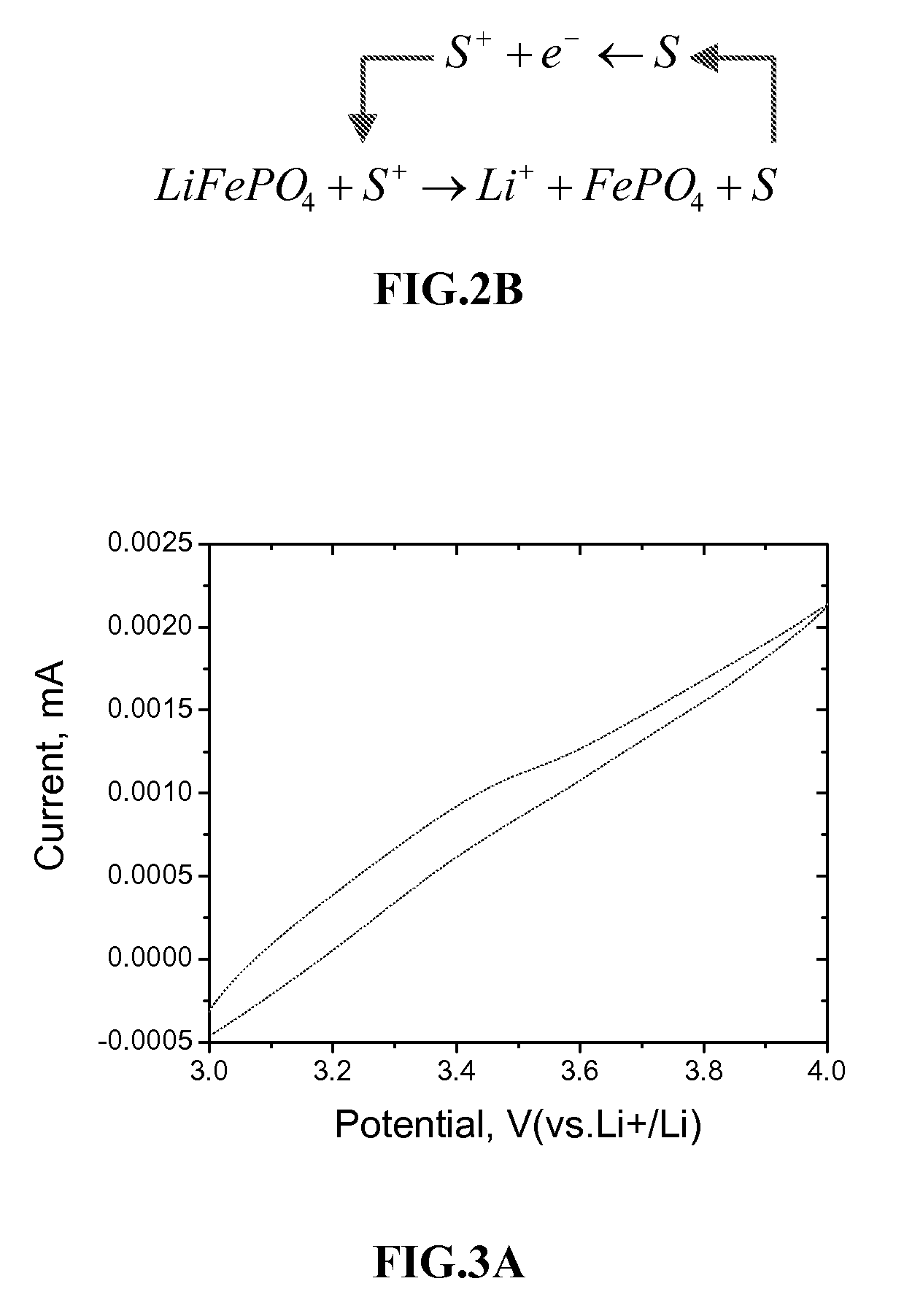
[0065]LiFePO4 powder with particle size distribution of 200˜700 nm was mixed with PVDF and acetylene black in weight ratio of 95:5. A 1.0 cm×1.0 cm electrode sheet comprising 10 μm thick same was used as working electrode, with lithium foil as counter and reference electrodes for electrochemical test. The three electrodes were separated to three compartments by glass frits and filled with EC+DMC (1:1) / 1M LiPF6 electrolyte. In the LiFePO4 electrode compartment, 0.032 M Os(mobpy)3Cl2 and Os(mbpy)3Cl2 was dissolved therein. The volume of electrolyte in cathodic compartment is 30 μl.

[0066]FIG. 3B shows the CV of the electrode system at different scan rates. The finite length diffusion of the compound within the electrode film renders the limiting current being independent of the scan rates. As the potential is higher than 3.55V (vs.Li+ / Li), both Os complexes are oxidized at current collector. Charges (holes) are transported from the current collector to LiFePO4 by the diffusion of the o...

example 1

Materials

[0195]LiFePO4 was synthesized by a variant of solid state reaction [15] employing FeC2O4.2H2O and LiH2PO4 as precursors. Their stoichiometric amounts were mixed and ground in a planetary ball-milling machine for 4 h. Then the powder was calcined in a tube furnace with flowing Ar—H2 (92:8 v / v) at 600° C. for 24 h. After cooling down to room temperature, the sample was ground in agate mortar. The BET surface area of the powder was ca. 5 m2 / g with an average particle size of 400 nm. X-ray diffraction confirmed the phase purity. The Ru-bipyridine complex, NaRu(4-carboxylic acid-4′-carboxylate(4,4′-dionyl-2,2′bipyridine)(NCS)2, coded as Z-907Na was synthesized as described elsewhere [16]. Single walled carbon nanotubes were grown by catalytic laser ablation method. The average diameter of tubes was determined by Raman and Vis-NIR spectroscopy to be ca. 1.3-1.4 nm. Other chemicals were from commercial sources and were used as received.

[0196]SWCNT were dispersed with solutions of ...


PUM


Abstract

This invention concerns a lithium rechargeable electrochemical cell containing electrochemical redox active compounds in the electrolyte. The cell is composed of two compartments, where the cathodic compartment comprises a cathodic lithium insertion material and one or more of p-type redox active compound(s) in the electrolyte; the anodic compartment comprises an anodic lithium insertion material and one or more of n-type redox active compound(s) in the electrolyte. These two compartments are separated by a separator and the redox active compounds are confined only in each compartment. Such a rechargeable electrochemical cell is suitable for high energy density applications. The present invention also concerns the general use of redox active compounds and electrochemically addressable electrode systems containing similar components which are suitable for use in the electrochemical cell.

Description

FIELD OF THE INVENTION[0001]This invention concerns electrochemically addressable lithium insertion electrode systems for electrochemical cells using non-aqueous organic electrolytes, quasi-solid gel electrolytes, solid electrolytes, or the like and in particular the use of said electrolytes in combination with porous electrode materials, i.e. doped or non-doped nanoparticles or sub-microparticles of lithium insertion materials and redox active compounds in the electrolyte. This invention also concerns the configuration of the electrochemical cell containing the redox active compounds.STATE OF THE ART[0002]Electrochemical cells, as illustrated in FIG. 1, have used lithium insertion materials by adding conductive additive, i.e. carbon black, carbon fiber, graphite, or mixture of them to improve the electronic conductivity of the electrode films.[0003]The lithium insertion materials in commercial electrochemical cells comprise 2˜25 wt. %, typically 10 wt. % conductive additives. These...

Claims


Application Information

Patent Timeline
IPC IPC(8): H01M6/16H01M4/60H01M4/62H01M4/52H01M4/50H01M4/58H01M4/48H01M4/13H01M10/0525H01M10/0562H01M10/0565H01M10/0567H01M10/058H01M10/36
CPCH01B1/122H01M4/13H01M4/5825H01M10/0525Y02E60/122H01M10/0565H01M10/0567H01M10/058H01M2300/0025H01M10/0562Y02E60/10Y02P70/50H01M10/052B82Y30/00H01M4/36H01M4/48H01M4/131H01M4/136H01M4/525H01M4/505H01M4/62H01M2004/021
Inventor EXNAR, IVANWANG, QINGGRATZEL, MICHAELZAKEERUDDIN, SHAIK MOHAMMEDKAVAN, LADISLAV
Owner DOW GLOBAL TECH LLC
Why Eureka
Try Eureka