High-Speed Receiver Architecture

a receiver and high-speed technology, applied in the field of high-speed data communication, can solve the problems of difficult and expensive to build with the required resolution, many challenges to implement 10 g systems, and various other components in the receiver may also be difficult or expensive to build at this speed of operation

Active Publication Date: 2009-07-23
MARVELL ASIA PTE LTD
View PDF38 Cites 35 Cited by
  • Summary
  • Abstract
  • Description
  • Claims
  • Application Information

AI Technical Summary

Benefits of technology

[0008]The present invention overcomes the limitations of the prior art by providing a receiver and/or transceiver with various features or combinations of features. In one aspect, the receiver includes an interleaved ADC coupled to a multi-channel equalizer that can provide different equalization for different ADC channels within the interleaved ADC. That

Problems solved by technology

However, there are many challenges to implementing 10 G systems, especially over multi-mode fibers.
However, a 10 G system requires a 10 G ADC, which can be difficult and expensive to build with the required resolution.
More generally, various other components in the receiver may also be difficult or expensive to

Method used


Image

  • High-Speed Receiver Architecture
  • High-Speed Receiver Architecture
  • High-Speed Receiver Architecture

Examples


Embodiment Construction

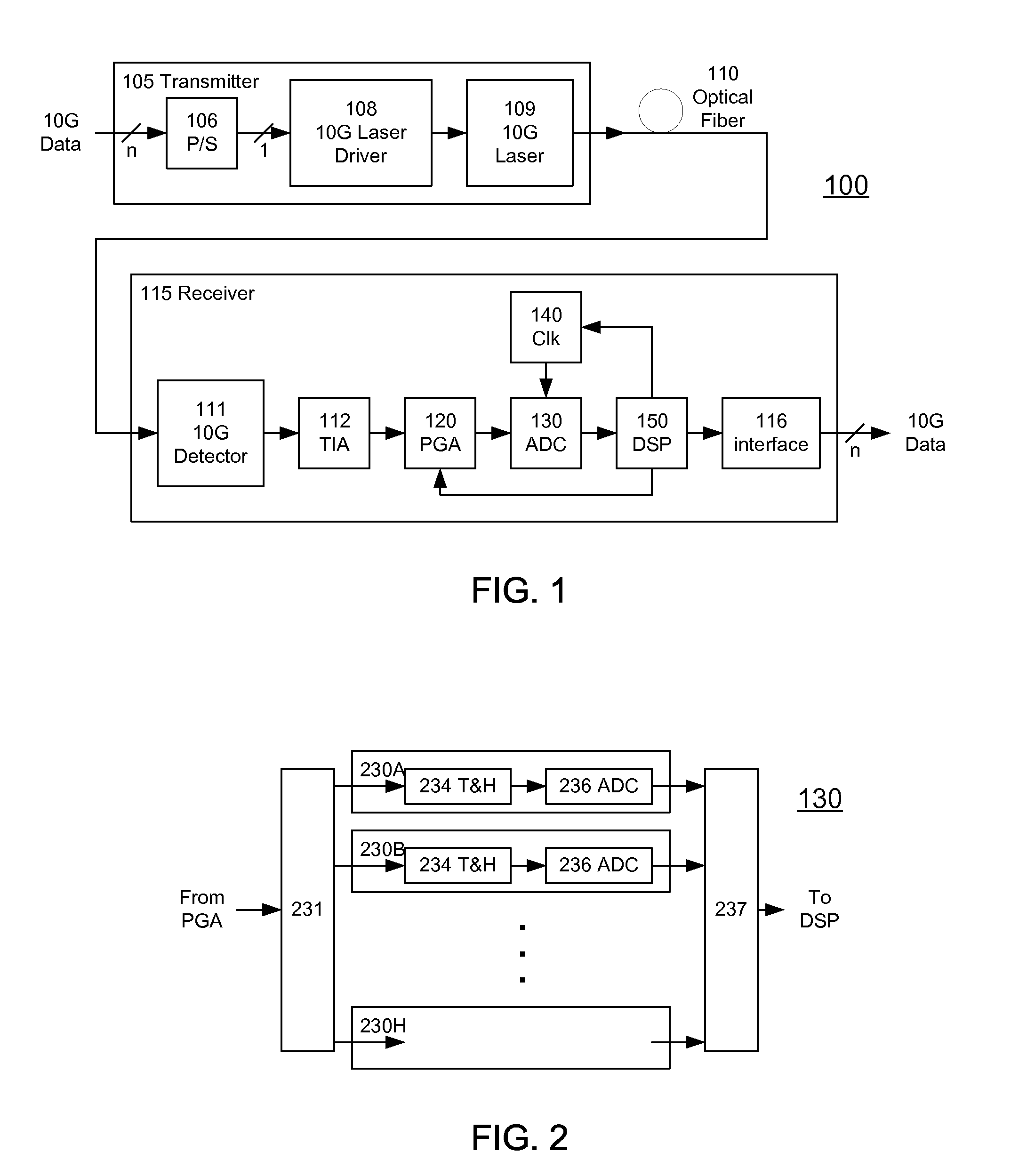
[0043]FIG. 1 shows an optical fiber communications link 100 according to the invention. The link 100 includes a transmitter 105 coupled through optical fiber 110 (the communications channel) to a receiver 115. A typical transmitter 105 may include a serializer or parallel / serial converter (P / S) 106 for receiving data from a data source on a plurality of parallel lines and providing serial data to a laser driver 108. The driver 108 then drives a laser source 109, for example a 1310 nm Fabry-Perot or DFB laser. The laser source 109 launches the optical waveform carrying the digital data on optical fiber 110.

[0044]On the receive side, a typical receiver 115 includes a photodetector 111 for receiving and detecting data from the optical fiber 110. The detected data is typically processed through a transimpedance amplifier (TIA) 112. A programmable gain amplifier (PGA) 120 applies a variable gain to the electrical analog signal. The resulting electrical signal is converted to digital form...


PUM


Abstract

A receiver (e.g., for a 10 G fiber communications link) includes an interleaved ADC coupled to a multi-channel equalizer that can provide different equalization for different ADC channels within the interleaved ADC. That is, the multi-channel equalizer can compensate for channel-dependent impairments. In one approach, the multi-channel equalizer is a feedforward equalizer (FFE) coupled to a Viterbi decoder, for example a sliding block Viterbi decoder (SBVD); and the FFE and/or the channel estimator for the Viterbi decoder are adapted using the LMS algorithm.

Description

CROSS-REFERENCE TO RELATED APPLICATION(S)[0001]This application (1) is a continuation-in-part of U.S. Utility patent application Ser. No. 12 / 056,084, “High-Speed Receiver Architecture,” filed Mar. 26, 2008 by Oscar E. Agazzi et al., which claims priority under 35 U.S.C. § 119(e) to U.S. Provisional Patent Application Ser. No. 60 / 908,149, “Digital Timing Recovery for Multimode Fibers in the Presence of Time Variations,” filed Mar. 26, 2007 by Mario R. Hueda; (2) is a continuation-in-part of U.S. Utility patent application Ser. No. 11 / 559,850, “High-Speed Receiver Architecture,” filed Nov. 14, 2006 by Oscar Agazzi et al.; which application claims priority under 35 U.S.C. § 119(e) to (a) U.S. Provisional Patent Application Ser. No. 60 / 737,103, “EDC Transceiver: System and Chip Architecture,” filed Nov. 15, 2005 by Oscar E. Agazzi et al., (b) U.S. Provisional Patent Application Ser. No. 60 / 779,200, “MIMO / MLSE Receiver for Electronic Dispersion Compensation of Multimode Optical Fibers,” ...

Claims


Application Information

Patent Timeline
IPC IPC(8): H04L27/01
CPCH03M1/0626H04L25/03038H03M1/0695H03M1/1042H03M1/1215H03M1/181H03M1/42H03M1/44H04L1/0054H04L1/0071H04L7/0004H04L7/0062H04L7/0083H04L7/0087H04L25/0204H03M1/0692
Inventor AGAZZI, OSCAR E.CRIVELLI, DIEGO E.CARRER, HUGO S.HUEDA, MARIO R.LUNA, GERMAN C.GRACE, CARL
Owner MARVELL ASIA PTE LTD
Why Eureka
Try Eureka