Medical implant

a technology of medical implants and implants, applied in the field of medical implants, can solve the problems of high energy cost required for maintaining the molten metal in a superheated state, difficult to control the decomposition (degradation) rate of medical implants in living organisms, and material limitations, and achieves low material strength, high ductility, and high strength.

Inactive Publication Date: 2009-07-30
TERUMO KK
View PDF6 Cites 45 Cited by
  • Summary
  • Abstract
  • Description
  • Claims
  • Application Information

AI Technical Summary

Benefits of technology

[0008]Furthermore, it is preferable that the rate of decomposition (degradation) of the stent in the living organism can be controlled as desired. For this purpose, the material (composition) of the stent has to be selected.
[0009]Thus, a stent is required to be comprised of a biodegradable material which is not limited in composition and which has both a high strength and a high ductility.
[0010]As an example of the stent comprised of a biodegradable material, the Igaki-Tamai Stent may be mentioned (refer to, for example, Non-patent Document 1). In this stent, polylactic acid, which is a biodegradable polymer, is used as the material, so that the stent is decomposed in the living body and shows the above-mentioned advantageous effects (a) to (d).
[0011]However, such a biodegradable stent comprised of a biodegradable polymer as just-mentioned is low in strength of material. In order to obtain a required radial force by compensating for the low material strength, the thi

Problems solved by technology

However, this method is applicable only where an Al-containing Mg alloy is used, and, therefore, the method has limitations in regard of material.
The limitation on material makes it difficult to control the decomposition (degradation) rate of the medical implant in a living organism.
In addition, the superheating treatment technique applied here has the problem of h

Method used


Image

  • Medical implant
  • Medical implant

Examples


example 1

[0169]As a specimen, an AZ31B alloy was prepared.

[0170]The specimen was subjected to a solution treatment at 700K for 36000 sec by an electric furnace, then to hot rolling (draft per pass: about 5%; final draft: 50%) at 573K, and to annealing at 473K for 36000 sec.

[0171]Here, the specimen after the solution treatment (referred to Specimen 1) and the specimen after the annealing (referred to Specimen 2) were observed microscopically. The microscope was an optical microscope (produced by Leica Inc.), and the magnification was 100 to 1000.

[0172]While Specimen 1 had a crystal grain diameter of about 30 to 70 μm, Specimen 2 had a crystal grain diameter of about 3 to 8 μm. Thus, refining of crystal grains was achieved by rolling and annealing.

[0173]From Specimens 1 and 2, specimens having a thikness of 0.65 mm, a width of 3 mm and a length of 6 mm were obtained by cutting in parallel to the rolling direction (the thus obtained specimens are referred to respectively as Specimen 10 and Spec...

example 2

[0174]From Specimen 2, a square rod member having a thickness of 8 mm, a width of 8 mm and a length of 100 mm was obtained by cutting, and was subjected to centerless polishing, to obtain a round rod member having a diameter of 3 mm. A through-hole with a section diameter of 2.4 mm was bored inside the round rod member by lathe machining, to produce a pipe. The pipe was hot drawn at 573K, to obtain a pipe having an outer diameter of 2 mm and an inner diameter of 1.6 mm.

[0175]Upon observation of the pipe under the same microscope as Example 1 and in the same conditions as above, the crystal grain diameter was found to be 2 to 3 μm. Thus, a further refining was confirmed. This is considered to be attributable to dynamic recrystallization during the hot drawing.

example 3

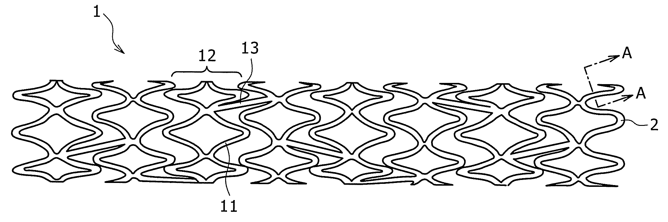
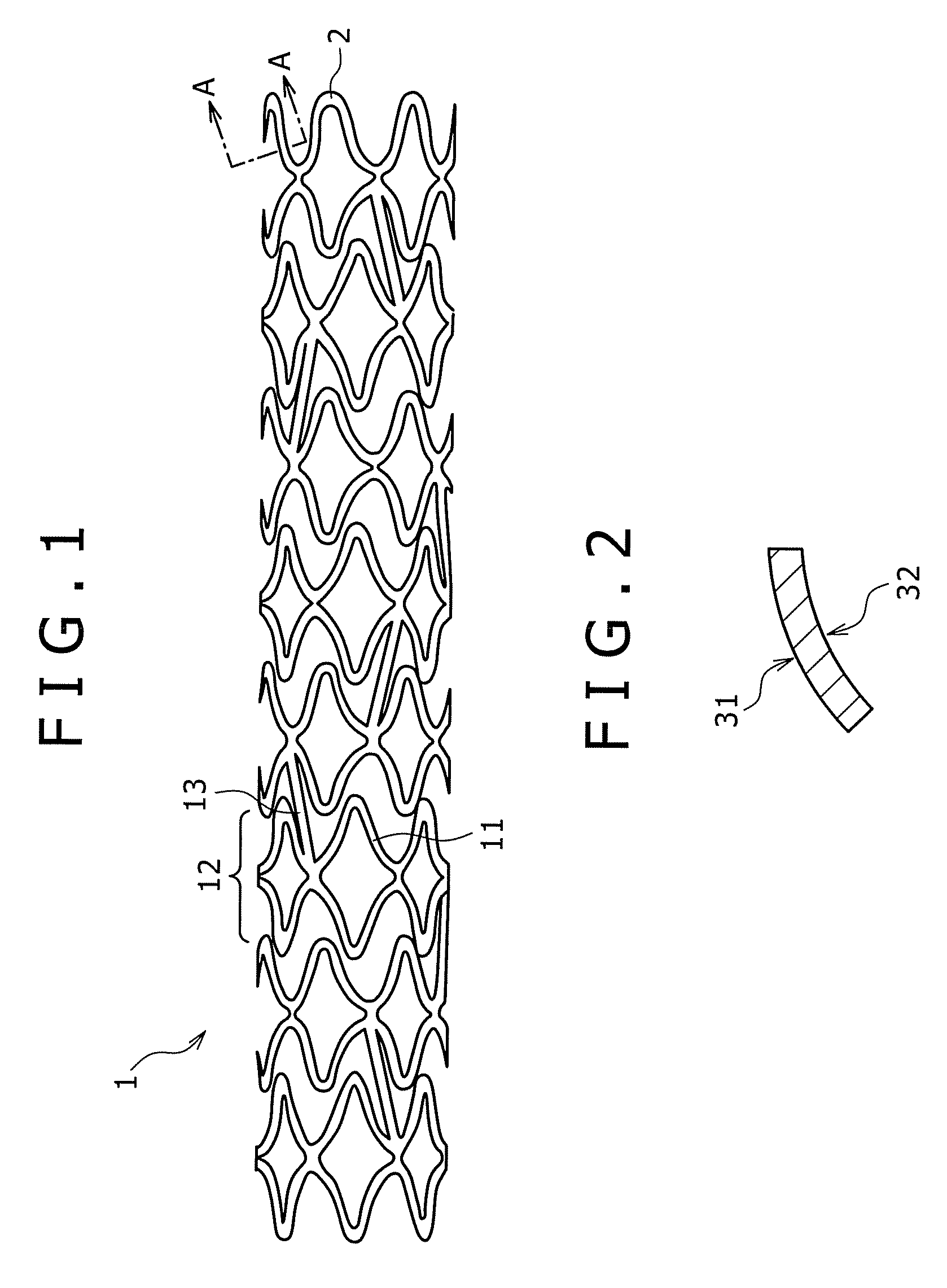
[0176]The pipe produced in Example 2 was subjected to laser beam machining, to produce a stent having a diameter of 2 mm and a length of 15 mm. The stent was expanded to a diameter of 3 mm by a balloon catheter. The stent showed no broken portion even upon expanding. It was thus confirmed that a stent suited to practical use can be produced in this manner.


PUM

PropertyMeasurementUnit
Diameteraaaaaaaaaa
Massaaaaaaaaaa
Massaaaaaaaaaa

Abstract

Disclosed herein is a medical implant including an implant body of which at least a part is comprised of a biodegradable metal, wherein the part comprised of the biodegradable metal has a crystal grain diameter of not more than 10 μm.

Description

BACKGROUND OF THE INVENTION[0001]1. Field of the Invention[0002]The present invention relates to a medical implant for use in therapy of a diseased portion of the living body of a human being or other animal.[0003]2. Description of the Related Art[0004]The medical implant relating to the present invention includes a variety of implants such as stent, balloon, cannula, catheter, artificial blood vessel, stent graft, etc. The following description will be made by taking a stent as an example of the medical implant.[0005]A stent is a medical implant which is implanted in a lumen such as a blood vessel, a lymph vessel, a bile duct, a ureter, etc. so as to retain an appropriate lumen diameter and to secure crossability of the lumen.[0006]The material constituting the stent is required to have both of a high strength and a high ductility, which are contradictory properties. If the strength is low, a radial force (strength in the radial direction) required of a stent cannot be obtained. If...

Claims


Application Information

Patent Timeline
IPC IPC(8): A61F2/06A61F2/915A61L27/00A61L29/00A61L31/00A61M29/00
CPCA61F2/042A61F2/90A61F2002/041A61F2002/048A61F2210/0004A61F2250/003A61F2220/0016A61L27/58A61L31/022A61L31/04A61L31/10A61L31/148A61L27/34
Inventor NAGURA, HIROAKIKAWAMURA, YOSHIHITOYAMASAKI, MICHIAKI
Owner TERUMO KK
Why Eureka
Try Eureka