
Highly heat conductive insulating member, method of manufacturing the same and electromagnetic device

a technology of high heat conductivity and insulating member, which is applied in the direction of plastic/resin/waxes insulators, natural mineral layered products, transportation and packaging, etc., can solve the problems of limited use of reference techniques, insufficient documents, and insufficient heat conductivity of electro-insulating members, etc., to achieve high heat conductivity, high heat conductivity, and easy manufacturing

Inactive Publication Date: 2009-08-06
OKAMOTO TETABUSHI +9
View PDF4 Cites 2 Cited by
  • Summary
  • Abstract
  • Description
  • Claims
  • Application Information

AI Technical Summary

Benefits of technology

[0011]The object of the present invention is to provide a widely usable highly heat conductive insulating member that can exhibit a highly heat conductive without having to use very limited components of resin and that can be easily manufactured, as well as a method of manufacturing the insulating member. Further, the object includes the provision of an electromagnetic coil that employs such a highly heat conductive insulating member.
[0019]It is preferable that the diameter of the first particles should be set in a range of 0.05 μm or more and 100 μm or less (50 nm to 105 nm). If the diameter of the first particles is less than 0.05 μm, it becomes difficult to disperse the particles uniformly in the layer, and as a result, the electric breakdown strength may be deteriorated in some cases. On the other hand, if the diameter of the first particles exceeds 100 μm, the flatness of the tape member or sheet member is impaired, and further the thickness becomes uneven easily.
[0022]The second particles are made of one or more types selected from the group consisting of boron nitride, carbon, aluminum nitride, aluminum oxide, magnesium oxide, silicon nitride, chromium oxide, aluminum hydroxide, artificial diamond, diamond-like carbon, carbon-like diamond, silicon carbide, gold, cupper, iron, laminar silicate clay mineral and mica. It is particularly preferable that the second particles are made of either one of carbon and aluminum oxide. Carbon particle such as of carbon black is appropriate for improving the heat conductivity λ of the material of the present invention. Further, aluminum oxide particle is suitable since it not only improves the heat conductivity λ of the material of the present invention but also it does not impair the insulating property of the material.
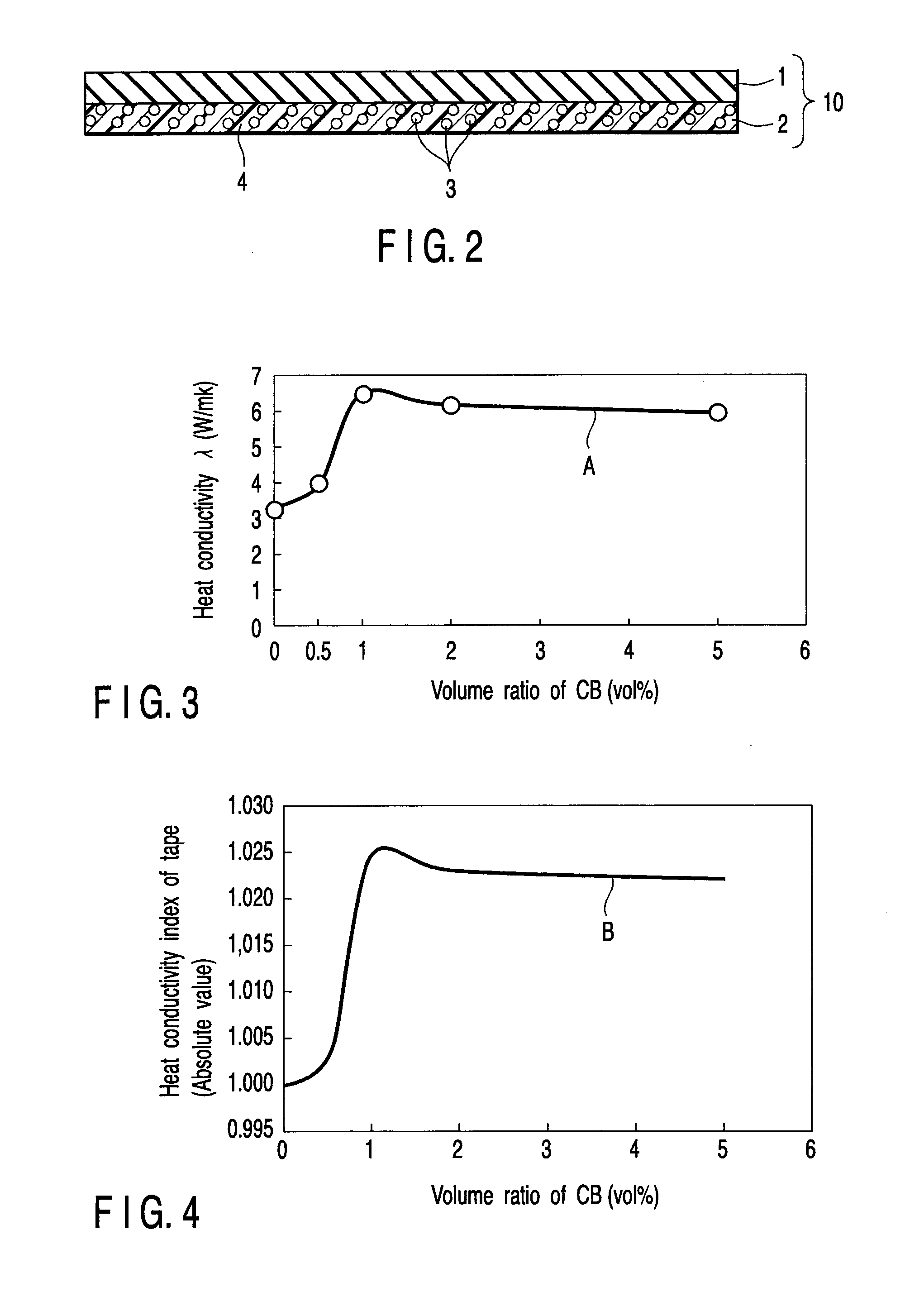
[0023]The content of the second particles in the backing material layer should preferably be set to 0.5% by volume or more, and most preferably, it should be set to 1% by volume or more. This is because if the content of the second particles is increased, the heat conductivity λ increases accordingly. In particular, if the content of the second particles is 1% by volume or more, the heat conductivity λ of the material dramatically improves as can be seen in FIG. 3 and FIG. 29.
[0031]As the above-mentioned solvent, water or various types of alcohols can be used, and it is preferable here that water should be used. In the case where the mica paper is used made using water, the steps S21 to S23 shown in FIG. 9 are employed. Mica scales have a high aspect ratio and therefore they easily aggregate to consolidate. Thus, even after the solvent volatilizes, the shape of the consolidated body is maintained and the highly heat conductive particles are well retained. It should be noted that when a slight amount of binder resin is added, the shape maintaining property and particle retaining property are improved.
[0036]The term “mica” used in this specification is meant to cover not only natural mica produced from the world of nature, but also artificial mica that is industrially manufactured. There are two types of mica, that is, calcined mica and non-calcined mica. It is preferable in the present invention that calcined mica should be used. The calcined mica, as it is calcined at a predetermined temperature, transforms further into scale-like shapes, thereby increasing the electric insulating property.

Problems solved by technology

However, the heat conductivity of the electro-insulating member of this prior art document is not sufficient, and further the resins that can be employed for this reference technique are limited to special components only.
However, in the insulating member of this prior art document, the heat conductive material that is used for the backing member does not exhibit a sufficiently high heat conductivity.
Thus, as an insulating layer of an electromagnetic coil, the heat conductivity is not sufficient.
However, the crystalline epoxy resin of this prior art document is in a solid state at room temperature, and therefore it is difficult to handle it.
However, in the electromagnetic coil of this prior art reference, the heat transmission is insulated by the mica layer, and therefore it is difficult to achieve a high heat conductivity.
As described above, the conventional insulating members entail such drawbacks that a sufficient heat conductivity cannot be obtained and the production takes much labor, time and high cost.

Method used


Image

  • Highly heat conductive insulating member, method of manufacturing the same and electromagnetic device
  • Highly heat conductive insulating member, method of manufacturing the same and electromagnetic device
  • Highly heat conductive insulating member, method of manufacturing the same and electromagnetic device

Examples


first embodiment

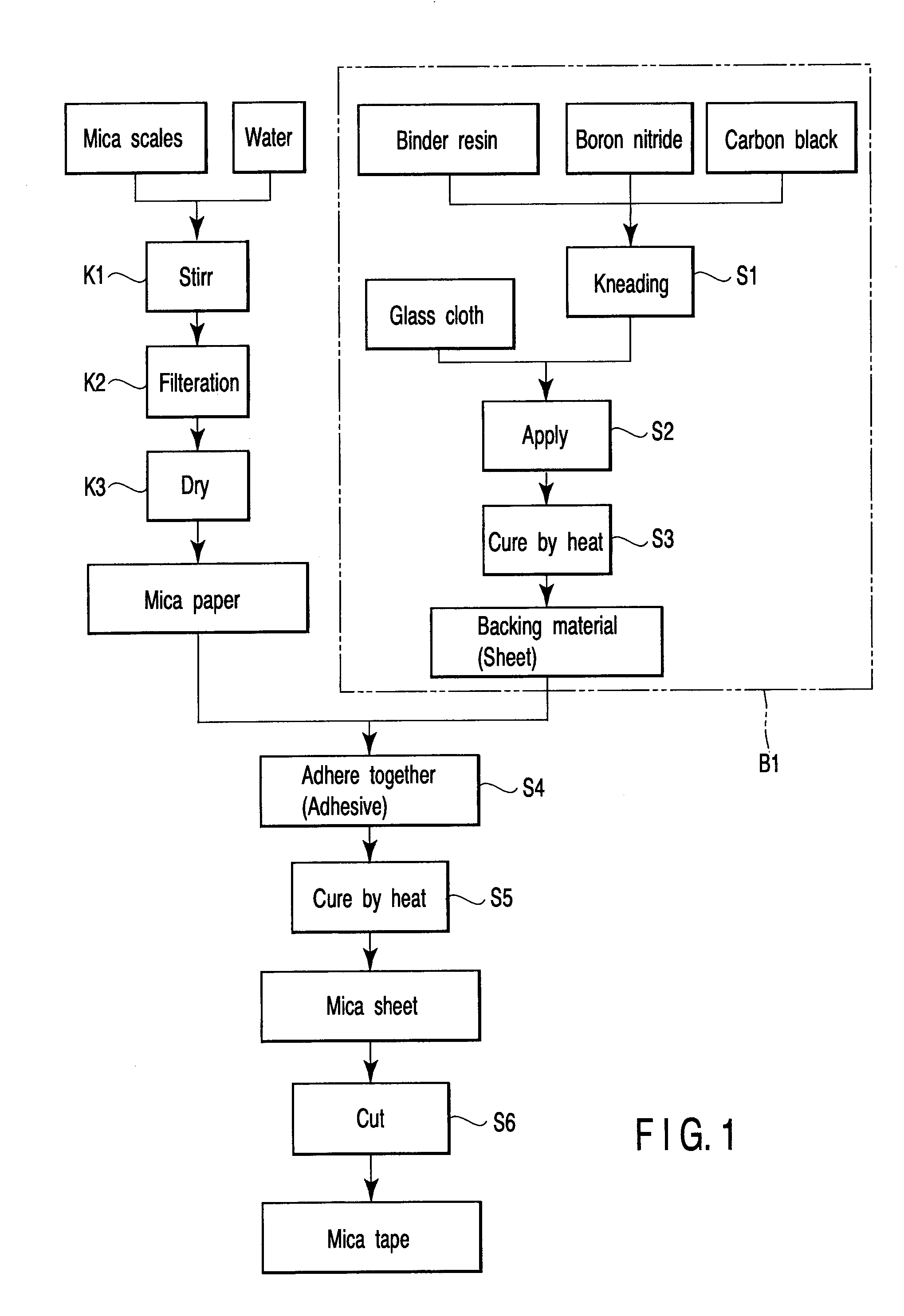
[0077]The first embodiment of the present invention will now be described with reference to FIGS. 1 to 8.

[0078]First, with reference to FIG. 1, the manufacture of the mica tape of this embodiment will be described.

[0079]300 cc of water was blended to 2.826 g of mica scales and the mixture was stirred (Step K1). Here, it is possible to add a slight amount of epoxy resin as the binder.

[0080]The thus obtained stirred mixture was allowed to pass a grid having a lattice size of, for example, 0.05 mm×0.05 mm in a manner of papermaking, thereby preparing a raw sheet (Step K2). The raw sheet was heated to a predetermined temperature and thus dried, thereby obtaining mica paper 1 (Step K3).

[0081]In a process B1 for manufacturing a backing material layer of this embodiment, first, a binder resin, boron nitride particles and carbon black particles were blended at a ratio of 24.7:74.2:1.1 and the mixture was kneaded (Step S1). In this embodiment, Asahi Thermal (Tradename) of Asahi Carbon Co., L...

second embodiment

[0108]Next, the second embodiment will now be described with reference to FIGS. 9 to 11.

[0109]In the member of this embodiment, highly heat conductive particles were filled in the mica layer side. As the backing material, glass cloth 25 was used. 2.83 g of mica scales and 0.125 g of alumina particles were blended to 3000 cc of water, and the mixture was stirred (Step S21). In this embodiment, NanoTekAl2O3-HT (product model number) of CI Kasei Company Ltd. was used as the alumina particles. The average diameter of the alumina particles was 70 nm. The shape of the alumina particles was spherical. As the mica particles, sintered mica was used. The average diameter of the mica scales was 15 μm.

[0110]The thus obtained stirred mixture was allowed to pass a grid having a lattice size of, for example, 0.05 mm×0.05 mm in a manner of papermaking, thereby preparing a raw sheet (Step S22). The raw sheet was heated to 120° C. and thus dried, thereby obtaining mica paper (Step S23).

[0111]The abov...

third embodiment

[0114]The third embodiment of the present invention will now be described with reference to FIG. 12. In a mica tape 10A of this embodiment, first particles having a heat conductivity of 0.5 W / mK or higher were filled and diffused in a mica layer 9. In this embodiment, a mica layer 11 was manufactured by an ordinary method and a heat conductive sheet 9 having a high heat conductivity was used as the backing material. In this case, the heat conductivity of the mica layer 11 is smaller as compared to that of the backing material layer 9, and therefore the mica layer 11 served as a heat barrier.

[0115]Here, while making the mica paper, alumina particles having an average particle diameter of 70 nm was blended into the mica paper. More specifically, the mica paper and the alumina particles were blended into distilled water and stirred, and the mixture was applied onto a cloth having a mesh of 0.05 μm. Then, the resultant was subjected to a dry process and thus a mica sheet was obtained. T...


PUM

PropertyMeasurementUnit
diameteraaaaaaaaaa
flatnessaaaaaaaaaa
average diameteraaaaaaaaaa

Abstract

The present invention provides a solution to the above-described drawbacks, and more specifically, as the tape-like or sheet-like insulation member, the resin matrix in which the first particles having a heat conductivity of 1 W / mK or higher and 300 W / mK or lower, that are diffused in the resin matrix, and the second particles having a heat conductivity of 0.5 W / mK or higher and 300 W / mK or lower, are diffused, is employed.

Description

CROSS REFERENCE TO RELATED APPLICATIONS[0001]This application is a divisional of, and claims the benefit of priority under 35 U.S.C. § 120 from, U.S. Ser. No. 11 / 028,227, filed Jan. 4, 2005, which is in turn a continuation of PCT Application No. PCT / JP03 / 08564, filed Jul. 4, 2003, which was published under PCT Article 21(2) in Japanese, and which is in turn based upon (as is the present application, which also claims the benefit of priority under 35 U.S.C. § 119 from) the Japanese Patent Applications No. 2002-196363, filed Jul. 4, 2002, and No. 2003-144919, filed May 22, 2003, the entire contents of each of which are incorporated herein by reference.BACKGROUND OF THE INVENTION[0002]1. Field of the Invention[0003]The present invention relates to a tape-like or sheet-like highly heat conductive insulating member used in an electromagnetic coil of an electromagnetic device such as a power generator, electric motor or transformer, and a method of manufacturing the insulating member. The...

Claims


Application Information

Patent Timeline
Patent Type & Authority Applications(United States)
IPC IPC(8): B32B9/00B32B5/16H01B3/00H01B3/30
CPCH01B3/006H01B3/30Y10T428/25Y10T428/2993Y10T428/2991Y10T428/2998Y10T428/2982Y10T428/256
Inventor OKAMOTO, TETSUSHITSUCHIYA, HIROYOSHISAWA, FUMIOIWATA, NORIYUKIKOYAMA, MITSUHIKOSUZUKI, YUKIOSUZUKI, AKIHIKOOOTAKA, TOORUISHII, SHIGEHITONAGANO, SUSUMU
Owner OKAMOTO TETABUSHI
Learn More