Eureka AIR delivers breakthrough ideas for toughest innovation challenges, trusted by R&D personnel around the world.

Vertical magnetic recording disk manufacturing method and vertical magnetic recording disk

a manufacturing method and magnetic recording technology, applied in the field of vertical magnetic recording disks, can solve the problems of inhibiting the increase in the recording density of magnetic disks, and achieve the effect of increasing the information recording density and enhancing the magnetic property

Active Publication Date: 2009-08-13
WESTERN DIGITAL TECH INC
View PDF14 Cites 70 Cited by
  • Summary
  • Abstract
  • Description
  • Claims
  • Application Information

AI Technical Summary

Benefits of technology

[0125]According to the present invention, it is possible to provide a method of manufacturing a vertical magnetic recording disk and the vertical magnetic recording disk which can enhance a magnetic property still more, thereby increasing an information recording density.

Problems solved by technology

As a result, a thermal stability of a recording signal is deteriorated by a superparamagnetic phenomenon so that a thermal fluctuating phenomenon is generated, that is, the recording signal is eliminated, causing an inhibition of an increase in a recording density of the magnetic disk.

Method used


Image

  • Vertical magnetic recording disk manufacturing method and vertical magnetic recording disk
  • Vertical magnetic recording disk manufacturing method and vertical magnetic recording disk

Examples


example 1

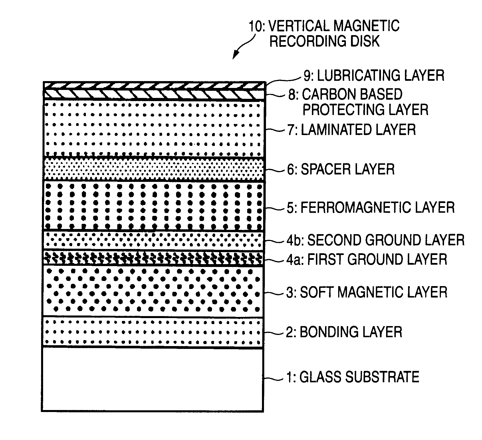
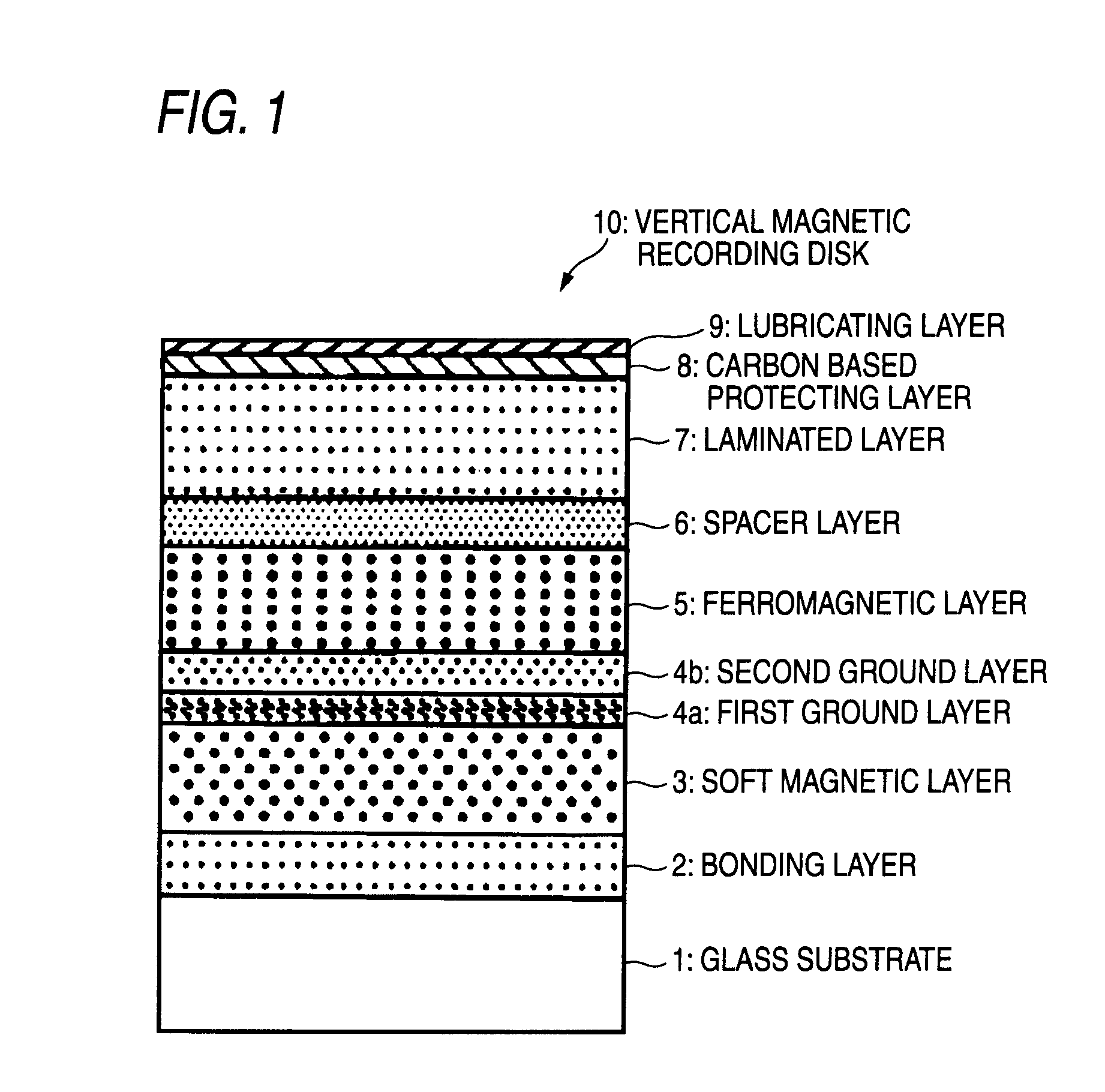
[0141]An amorphous aluminosilicate glass was molded in a disk-shape by a direct press and a glass disk was thus fabricated.

[0142]The glass disk was sequentially subjected to grinding, polishing and chemical strengthening so that a smooth non-magnetic glass substrate 1 formed by a chemical strengthened glass disk was obtained. A disk diameter is 65 mm.

[0143]A surface roughness of a main surface of the glass substrate 1 was measured by an atomic force microscope (AFM) so that a smooth surface shape having Rmax of 4.8 nm and Ra of 0.42 nm was observed. The Rmax and Ra conform to the Japanese Industrial Standard (JIS).

[0144]Next, the bonding layer 2 and the soft magnetic layer 3 were sequentially formed on the obtained glass substrate 1 in an Ar gas atmosphere through a DC magnetron sputtering method by using a film forming apparatus carrying out vacuuming.

[0145]At this time, the bonding layer 2 was formed using a CrTi target to obtain a CrTi (Cr: 55 at %, Ti: 45 at %) having a film thi...

example 2

[0184]A vertical magnetic recording disk was obtained in the same manner as in the example 1 except that the film thickness of the ferromagnetic layer 5 was set to be 13.5 nm, the film thickness of the spacer layer 6 was set to be 0.3 nm and the exchange energy control layer 7 was set to a film laminated in a cycle of CoPt having a thickness of 2.2 nm and Pd having a thickness of 0.4 nm (Example 2).

[0185]An orientation of a vertical magnetic recording layer in the obtained vertical magnetic recording disk was analyzed through an X-ray diffraction method. As a result, a c-axis of an hcp (hexagonal close-packed) crystal structure was oriented in a perpendicular direction to a disk surface in the same manner as in the example 1.

[0186]Moreover, the ferromagnetic layer 5 in the obtained vertical magnetic recording disk was analyzed in detail by utilizing a transmission electron microscope (TEM). As a result, a granular structure was observed in the same manner as in the example 1.

example 3

[0187]A vertical magnetic recording disk was obtained in the same manner as in the example 1 except that the first ground layer 4a was set to CoCrTa (Co: 55 at %, Cr: 35 at %, Ta: 10 at %) having a film thickness of 3 nm, the film thickness of the ferromagnetic layer 5 was set to 12 nm, the film thickness of the spacer layer 6 was set to 0.8 nm and the exchange energy control layer 7 was set to a film alternately laminated in three cycles of CoB (Co: 95 at %, B: 5 at %) having a thickness of 0.35 nm and Pd having a thickness of 0.8 nm (Example 3).

[0188]An orientation of a vertical magnetic recording layer in the obtained vertical magnetic recording disk was analyzed through an X-ray diffraction method. As a result, a c-axis of an hcp (hexagonal close-packed) crystal structure was oriented in a perpendicular direction to a disk surface in the same manner as in the example 1.

[0189]Moreover, the ferromagnetic layer 5 in the obtained vertical magnetic recording disk was analyzed in deta...


PUM

PropertyMeasurementUnit
thicknessaaaaaaaaaa
thicknessaaaaaaaaaa
thicknessaaaaaaaaaa

Abstract

In a method of manufacturing a magnetic disk including at least a magnetic recording layer on a substrate 1 and used for vertical magnetic recording, in a step of forming, on the substrate 1, the magnetic recording layer composed of a ferromagnetic layer 5 having a granular structure and an exchange energy control layer 7 constituted by a laminated layer formed on the ferromagnetic layer 5, at least the exchange energy control layer 7 is formed through sputtering in an atmosphere of a rare gas having a greater mass than an argon gas. The rare gas having a greater mass than the argon gas is a krypton (Kr) gas, for example. The exchange energy control layer 7 is a laminated layer composed of a first layer containing Co or a Co-alloy and a second layer containing palladium (Pd) or platinum (Pt), for example.

Description

TECHNICAL FIELD[0001]The present invention relates to a vertical magnetic recording disk to be loaded onto a magnetic disk device such as a hard disk drive (HDD) using a vertical magnetic recording system.BACKGROUND ART[0002]With a recent increase in a capacity of an information processing, various information recording techniques have been developed. In particular, a surface recording density of a hard disk drive (HDD) using a magnetic recording technique has been continuously increased at an annual rate of approximately 100%. Recently, there has been demanded an information recording capacity exceeding 60 Gbytes per 2.5-inch diameter magnetic disk to be used for the HDD. In order to meet the requirements, it has been demanded to implement an information recording density exceeding 100 Gbits per square inch.[0003]In order to achieve a high recording density in the magnetic disk to be used for the HDD, it has been required to microfabricate a magnetic crystal grain constituting a ma...

Claims


Application Information

Patent Timeline
Patent Type & Authority Applications(United States)
IPC IPC(8): G11B5/66C23C14/16
CPCG11B5/667G11B5/851G11B5/7325G11B5/73921G11B5/7364G11B5/7361G11B5/678
Inventor KIM, KONGDUMAYA, JO ALVIN
Owner WESTERN DIGITAL TECH INC
Why Eureka
Eureka Blog
Learn More