Grain Refiners for Steel-Manufacturing Methods and Use

Inactive Publication Date: 2009-08-27
SINVENT AS
View PDF6 Cites 13 Cited by
  • Summary
  • Abstract
  • Description
  • Claims
  • Application Information

AI Technical Summary

Benefits of technology

[0018]In one embodiment the invention provides a method for grain refinement of steel, wherein the grain refining composite material contains about 109 particles per mm3 of composition XaSb or XaOb, with a mean particle size of about 1 μm and a maximum spread in the particle diameters ranging from 0.2 to 5 μm. The corresponding volume fraction of particles in the composite material is about 0.5. Preferably, this said composite material is added to liquid steel in an amount of about

Problems solved by technology

This requirement is not possible to meet using the conventio

Method used


Image

  • Grain Refiners for Steel-Manufacturing Methods and Use
  • Grain Refiners for Steel-Manufacturing Methods and Use
  • Grain Refiners for Steel-Manufacturing Methods and Use

Examples


example 1

Manufacturing of a CeS Based PCGR

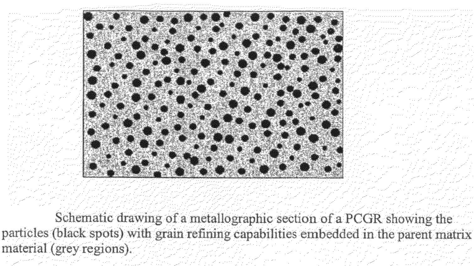
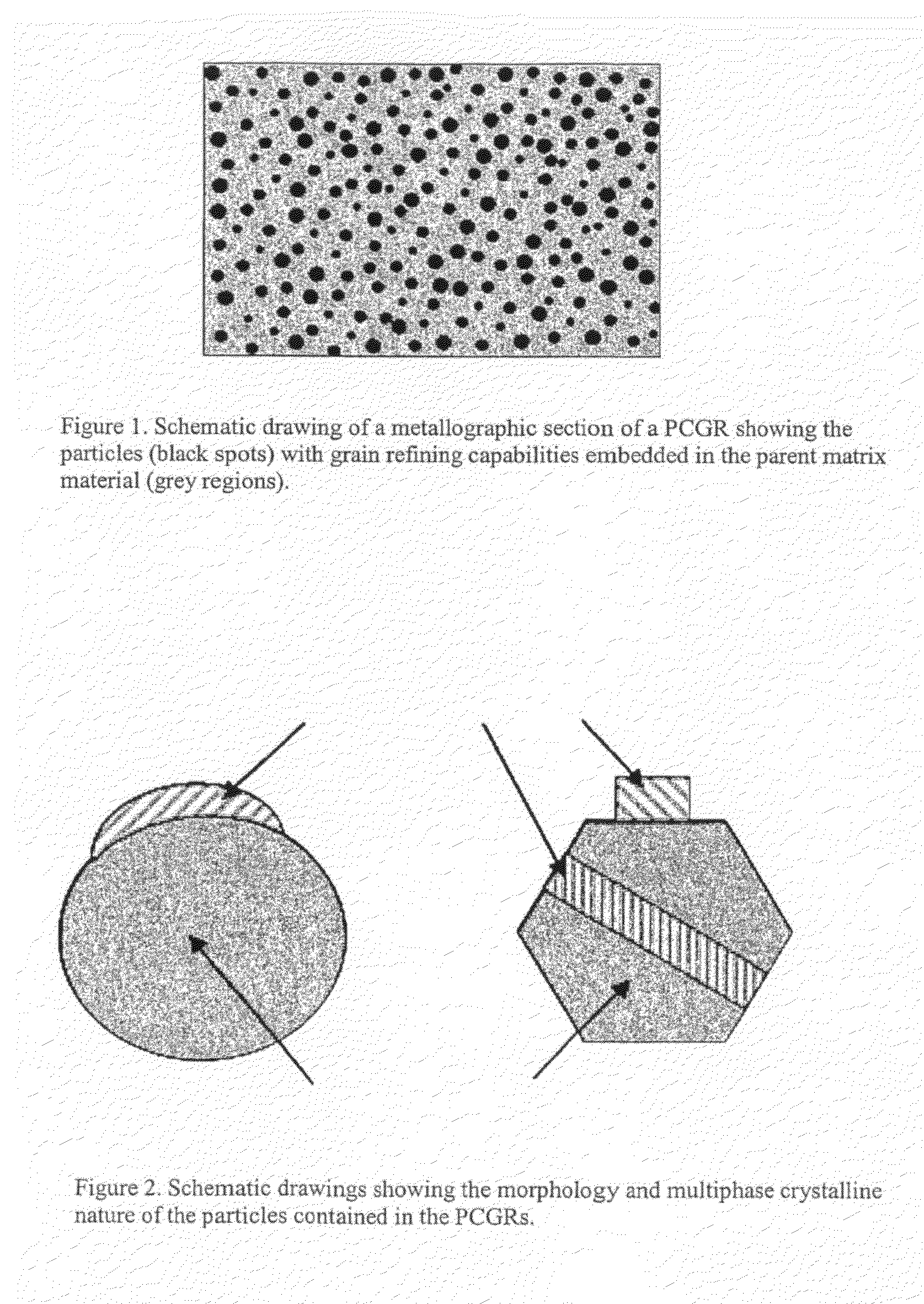
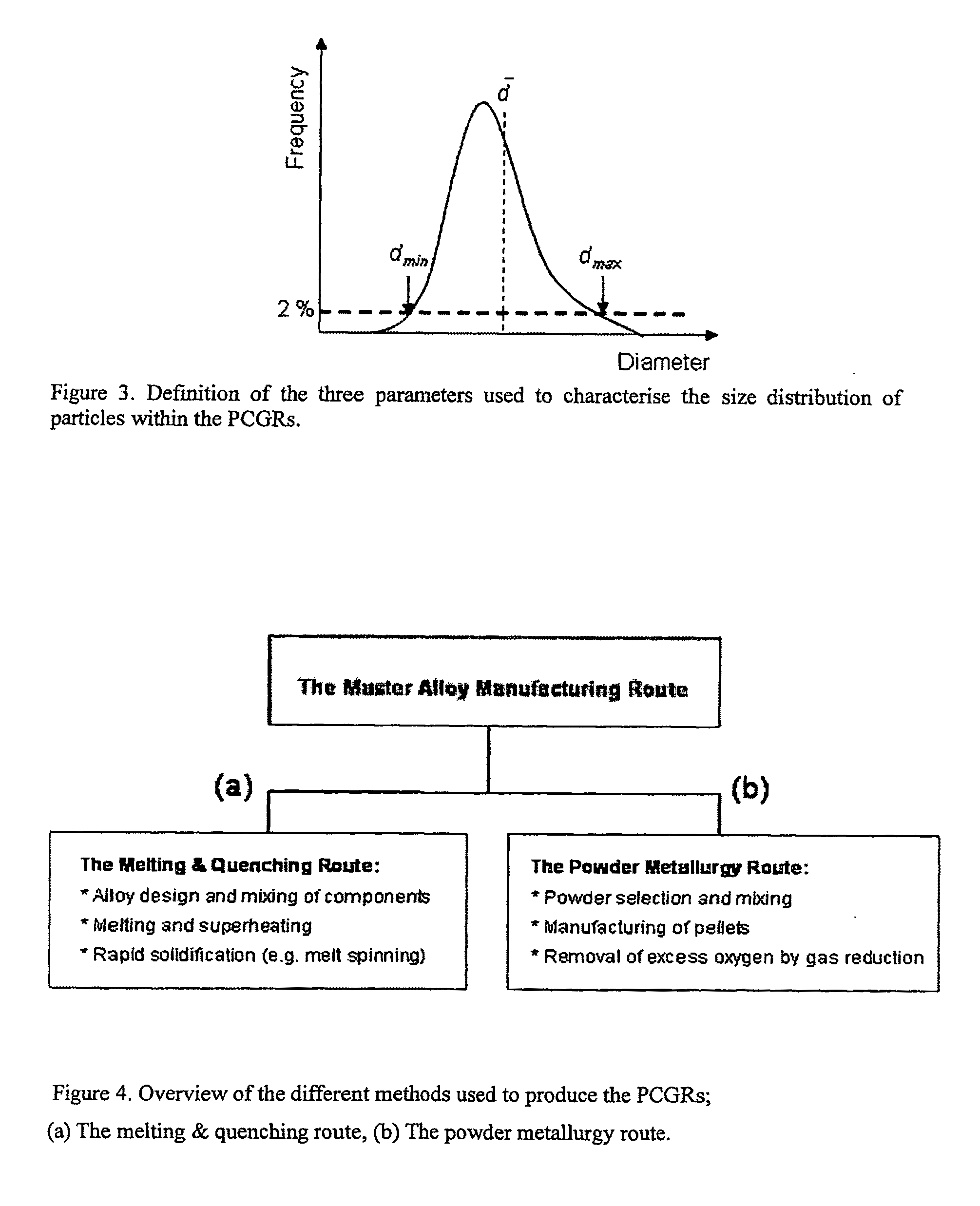
[0067]The CeS based PCGR shown in FIG. 5 was produced by the melting and quenching route in the laboratory. As a starting point small chips of Ce metal was mixed with FeS to achieve the target sulphur content of about 5% by weight. This mixture was then melted and superheated (˜100° C. above its melting point) in a Ta crucible under the shield of pure argon using induction heating. Following superheating the melt was rapidly quenched against a fast rotating copper wheel. The subsequent metallographic examination of the chilled metal ribbons revealed a very fine dispersion of CeS particles being embedded in a matrix of Ce+Fe, as shown by the optical micrograph in FIG. 5. In this case the mean diameter d of the CeS particles was found to be about 2 μm, with the maximum and minimum particle diameters being within the limits dmaxmin>0.4 μm, respectively.

example 2

Manufacturing of a TimOn Based PCGR

[0068]FIG. 6 is a line scan through a particle of partly reduced ilmenite (FeTiO3) showing formation of a metal shell around an oxide centre. It can be seen that the iron in the ilmenite diffuse out to the grain surface and the titanium is left behind in the form of rutile (TiO2). The starting material is ilmenite pellets made from ilmenite ore grains, oxidized at 800° C. in air, and subsequently reduced at 950° C. in an atmosphere of 99 vol % CO(g) and 1 vol % CO2(g). The reduction was discontinued after 2 hours at a stage where about 50% of the iron contained in the ilmenite was converted to metallic iron to show the transport of iron to the particle surface. On further reduction the outer metallic shell as well as the rutile will increase at the expense of the ilmenite core, giving an end product essentially consisting of a rutile core surrounded by metal.


PUM

PropertyMeasurementUnit
Temperatureaaaaaaaaaa
Lengthaaaaaaaaaa

Abstract

The present invention concerns a new type of grain refiners for steel, in the form of a particulate composite material, containing a high volume fraction of tailor-made dispersed particles, with the purpose of acting as potent heterogeneous nucleation sites for iron crystals during solidification and subsequent thermo-mechanical treatment of the steel. The material comprises a composition of particles of XaSb or XaOb and the element(s) X, where X is one or more elements selected from the group Ce, La, Pr, Nd, Y, Ti, Al, Zr, Ca, Ba, Sr, Mg, Si, Mn, Cr, V, B, Nb, Mo and Fe, and S is sulphur, (O is oxygen), wherein said material additionally contains oxygen, sulphur, carbon and nitrogen, wherein the sulphur (or oxygen) content is between 2 and 30% by weight of said material, while the total content of oxygen (or sulphur), carbon and nitrogen and said other elements selected from the group X is between 98 and 70% by weight of said material, and the said material contains a high volume fraction of finely dispersed XaSb or XaOb particles embedded in a metallic matrix X. The invention further concerns methods for production and use of the composite material.

Description

INTRODUCTION[0001]The present invention relates to a grain refining composite material for steel, methods of producing such grain refining composites for steel and methods for grain refinement of steel. The steel may be both ferritic and austenitic steels.BACKGROUND[0002]The demand for higher performance materials with optimum combinations of properties is steadily becoming more critical. For steels, the microstructure controls the resulting mechanical properties and hence, the desired property profile requires the development of a properly adjusted microstructure. The traditional way of producing a fine-grained microstructure yielding the optimum combination of strength and toughness is through thermomechanical processing. By such processing, an effective ferrite grain size well below 5 μm can readily be achieved, even in thick steel plates. In addition, the use of advanced ladle refining techniques for deoxidation and desulphurisation has lead to further quality improvements throu...

Claims


Application Information

Patent Timeline
IPC IPC(8): C21C7/00B22D11/11C22C14/00C22C16/00C22C21/00C22C22/00C22C23/00C22C24/00C22C27/02C22C27/04C22C27/06C22C28/00
CPCB22D11/108B22D11/11B22D11/111C21C7/0006B22D11/116C21C7/0056C21C7/0075B22D1/00C21C7/0037
Inventor GRONG, OYSTEINVAN DER EIJK, CASPERTRANELL, GABRIELLA MARIAKOLBEINSEN, LEIV OLAV
Owner SINVENT AS
Why Eureka
Try Eureka