Electron beam apparatus
a technology of electron beam and apparatus, which is applied in the field of electron beam apparatus, can solve the problems of increasing critical resolution, increasing processing speed, and sometimes largely increasing processing speed, so as to reduce the influence of space charge effect, increase processing speed, and reduce the light path length of the electron beam apparatus
- Summary
- Abstract
- Description
- Claims
- Application Information
AI Technical Summary
Benefits of technology
Problems solved by technology
Method used
Image
Examples
first embodiment
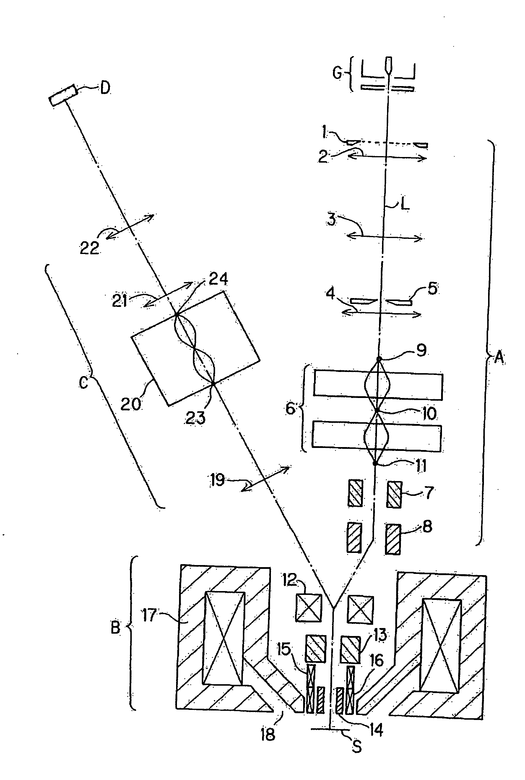
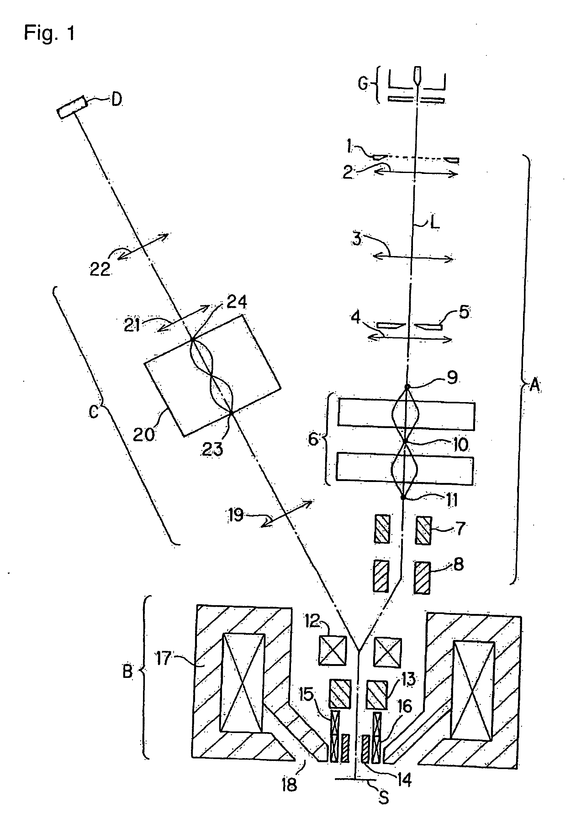
[0044]FIG. 1 is a diagram generally showing an electron beam apparatus according to the present invention. As shown in FIG. 1, the electron beam apparatus comprises: an electron gun G; an electro-optical system A for transporting a primary electron beam emitted from the electron gun G; an electro-optical system B for irradiating a sample S with the primary electron beam sent from the electro-optical system A and separating a secondary electron beam emitted from the sample S from the primary electron beam; an electro-optical system C for transporting the separated secondary electron beam; and a detector D for receiving the secondary electron beam from the electro-optical system C.
[0045]The electro-optical system A comprises a multi-aperture member 1, a condenser lens 2, reduction lenses 3, 4, NA aperture member 5, aberration correcting lens 6, a first scan deflector 7, and a pre-deflector 8 for beam separation. The aberration correction lens 6 comprises, for example, correction lense...
fourth embodiment
[0083]FIG. 5 shows a schematic diagram of an electron beam apparatus according to the present invention. This embodiment is a multi-beam SEM electron beam apparatus. In this electron beam apparatus, electron beams emitted from an electron gun G is irradiated to a plurality of apertures 2-1, and forms a reduced image at a position 4-1 by a reduction lens 3-1. Then, the electron beams are focused at positions 8-1 and 9-1 by a non-dispersion Wien-filter 5-1 and further reduced in scale by tablet lenses 10-1 and 17-1, and forms a reduced image of multi-beams on a sample S. The tablet lens 17-1 is a magnetic lens which comprises a magnetic gap 19-1 defined on a side of the lens closer to the sample S, and functions as an objective lens.
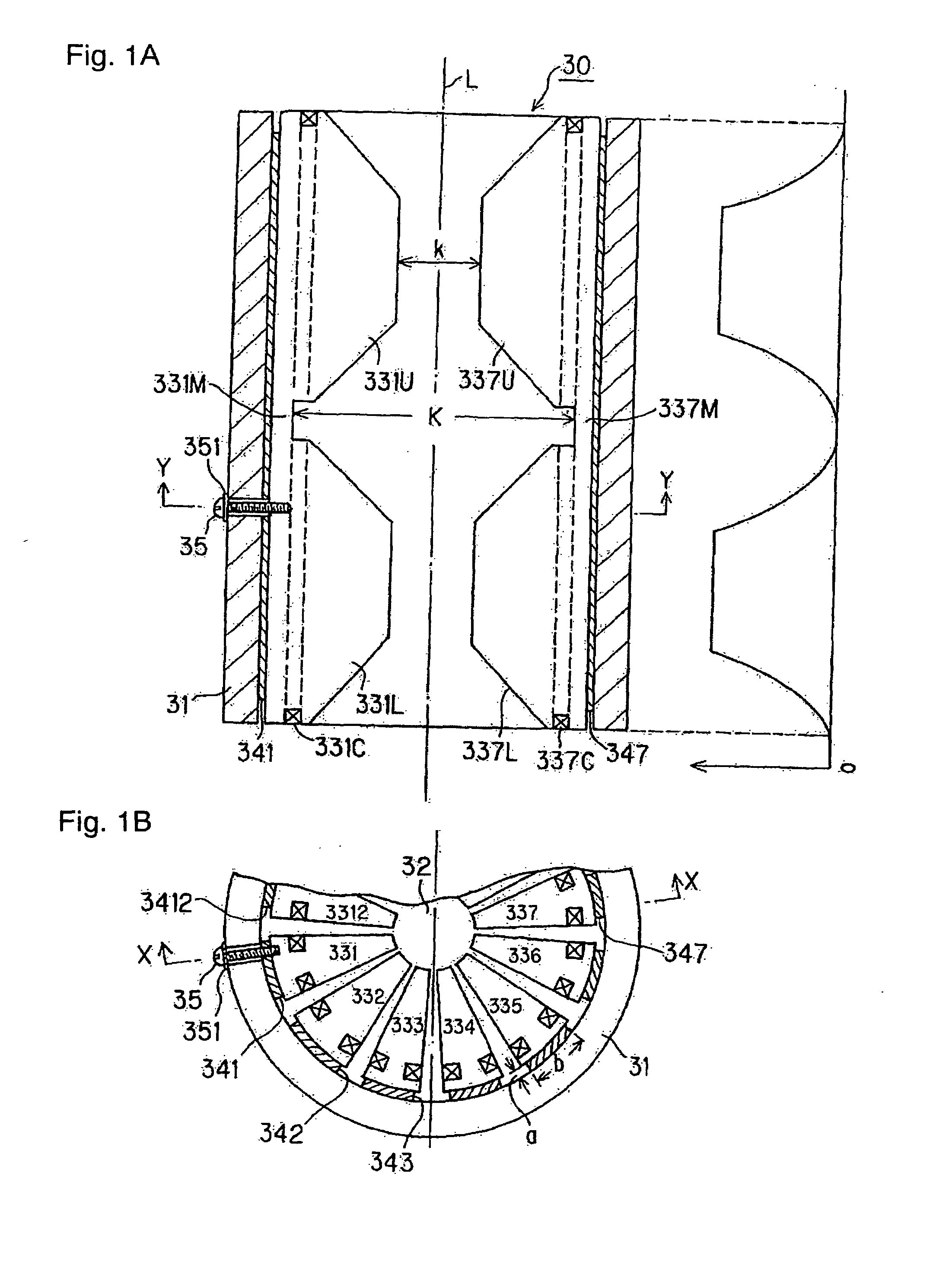
[0084]Describing in a more specific manner, the Wien-filter 5-1 is configured to perform a convergence action in two regions on the incident side and exiting side in which a bore diameter 6-1 is set smaller, and not to perform a filter action in a central ...
fifth embodiment
[0094]FIG. 6 shows an electron beam apparatus according to the present invention. In this embodiment, the electron beam apparatus comprises a projection electro-optical system. In this electron beam apparatus, an electron beam emitted from an electron gun G is irradiated to a rectangular aperture 32-1 at a uniform intensity, and a resulting rectangular primary electron beam is adjusted in reduction factor by lenses 33-1 and 34-1 at two stages, and is deflected by an electromagnetic deflector 35-1. Then, it is directed onto a sample S along a trajectory indicated by 38-1 (for example, in a range of 4 to 15°) through an objective lens 36.
[0095]Secondary electrons emitted from the sample S by the irradiation of the primary electron beam pass through the objective lens 36-1, is limited to an appropriate resolution by an NA aperture 40-1, is converged by the tablet lens 42-1, and generates a magnified image at an object point 43-1 of an axial chromatic aberration correcting lens 44-1. Th...
PUM
 Abstract
Description
Claims
Application Information
 - R&D
- Intellectual Property
- Life Sciences
- Materials
- Tech Scout
- Unparalleled Data Quality
- Higher Quality Content
- 60% Fewer Hallucinations
Browse by: Latest US Patents, China's latest patents, Technical Efficacy Thesaurus, Application Domain, Technology Topic, Popular Technical Reports.
© 2025 PatSnap. All rights reserved.Legal|Privacy policy|Modern Slavery Act Transparency Statement|Sitemap|About US| Contact US: help@patsnap.com


