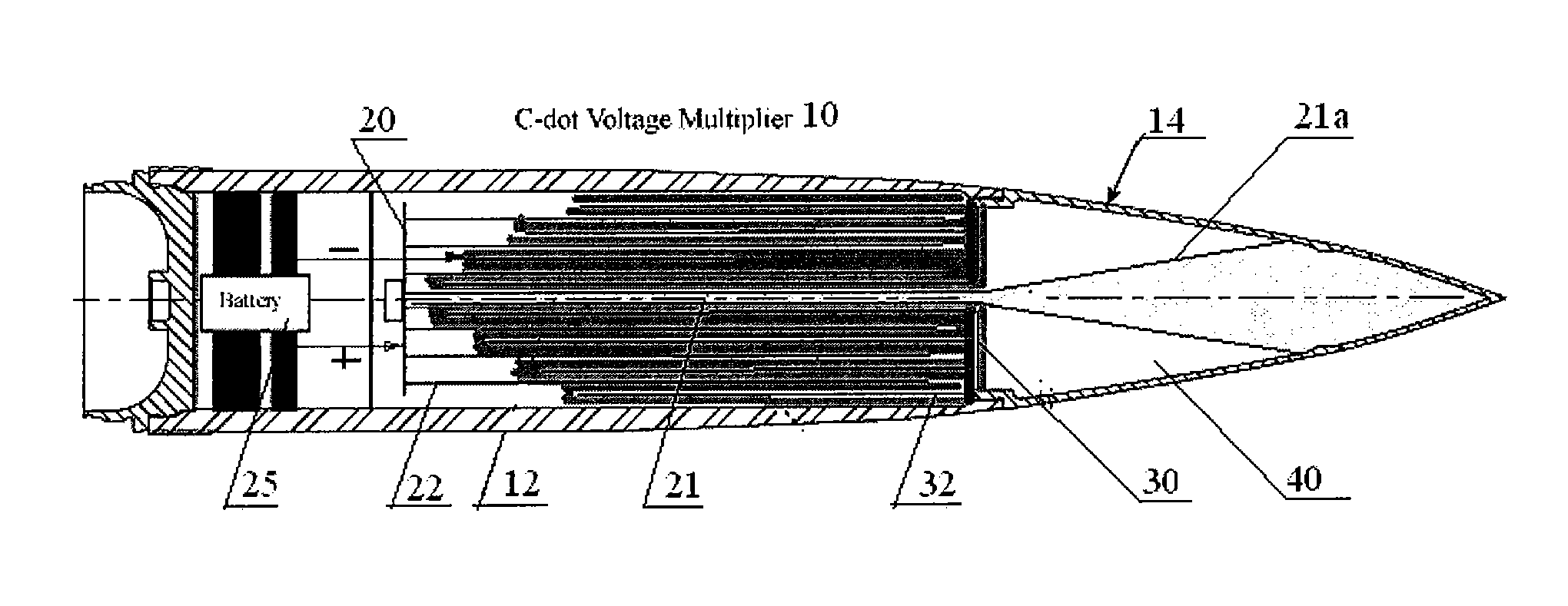
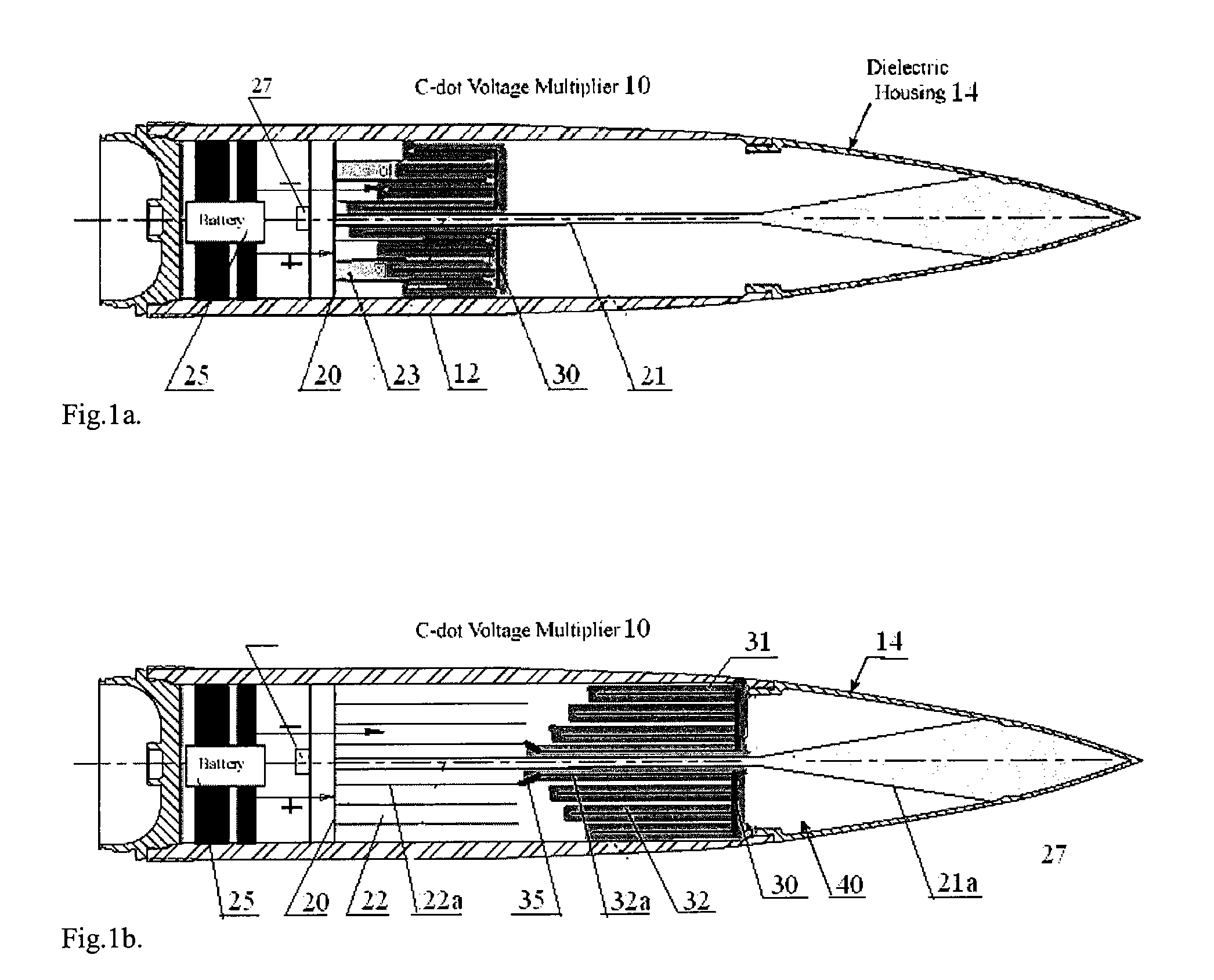
Systems and methods for generating high power, wideband microwave radiation using variable capacitance voltage multiplication

a technology of variable capacitance and multiplication, applied in the field of electromagnetic munitions, can solve the problems of reducing coupling power, difficult to predict coupling cross-section for a specific object, and almost any radiation pulse (with any frequency and any pulse duration) can penetrate through back-door coupling but with less efficiency, so as to reduce the overlap of capacitor plates, and increase the distance between capacitor plates

Inactive Publication Date: 2009-09-10
MICROWAVE SCI
View PDF3 Cites 22 Cited by
  • Summary
  • Abstract
  • Description
  • Claims
  • Application Information

AI Technical Summary

Benefits of technology

[0017]The capacitance can be decreased in different ways: for example, by increasing the distance between capacitor plates, or by reducing the area of overlap of the ca...

Problems solved by technology

Radiating at random angles or into the side-lobes of an antenna tends to reduce the coupled power, often substantially.
Therefore, the coupling cross-section is often difficult to predict for a specific object without detailed testing, although properties averaged over frequency bands can be predicted.
However, much fielded hardware typically uses pin-diodes.
It is clear that short, high-power pulses of narrow band radiation with defined frequency are preferred for suppression of operation of irradiated electronic devices through front-door coupling, whereas almost any radiation pulses (with any frequency and any pulse duration) can penetrate through back-door coupling but with less efficiency.
Once radiation penetrates into the interior of a target system, the susceptibility* of the small-scale semiconductor devices, which make up the interior electronics, becomes the important issue in HPM/UWB utility.
Failures in semiconductor devices due to thermal effects occur when the temperature at a critical j...

Method used


Image

  • Systems and methods for generating high power, wideband microwave radiation using variable capacitance voltage multiplication
  • Systems and methods for generating high power, wideband microwave radiation using variable capacitance voltage multiplication
  • Systems and methods for generating high power, wideband microwave radiation using variable capacitance voltage multiplication

Examples


examples

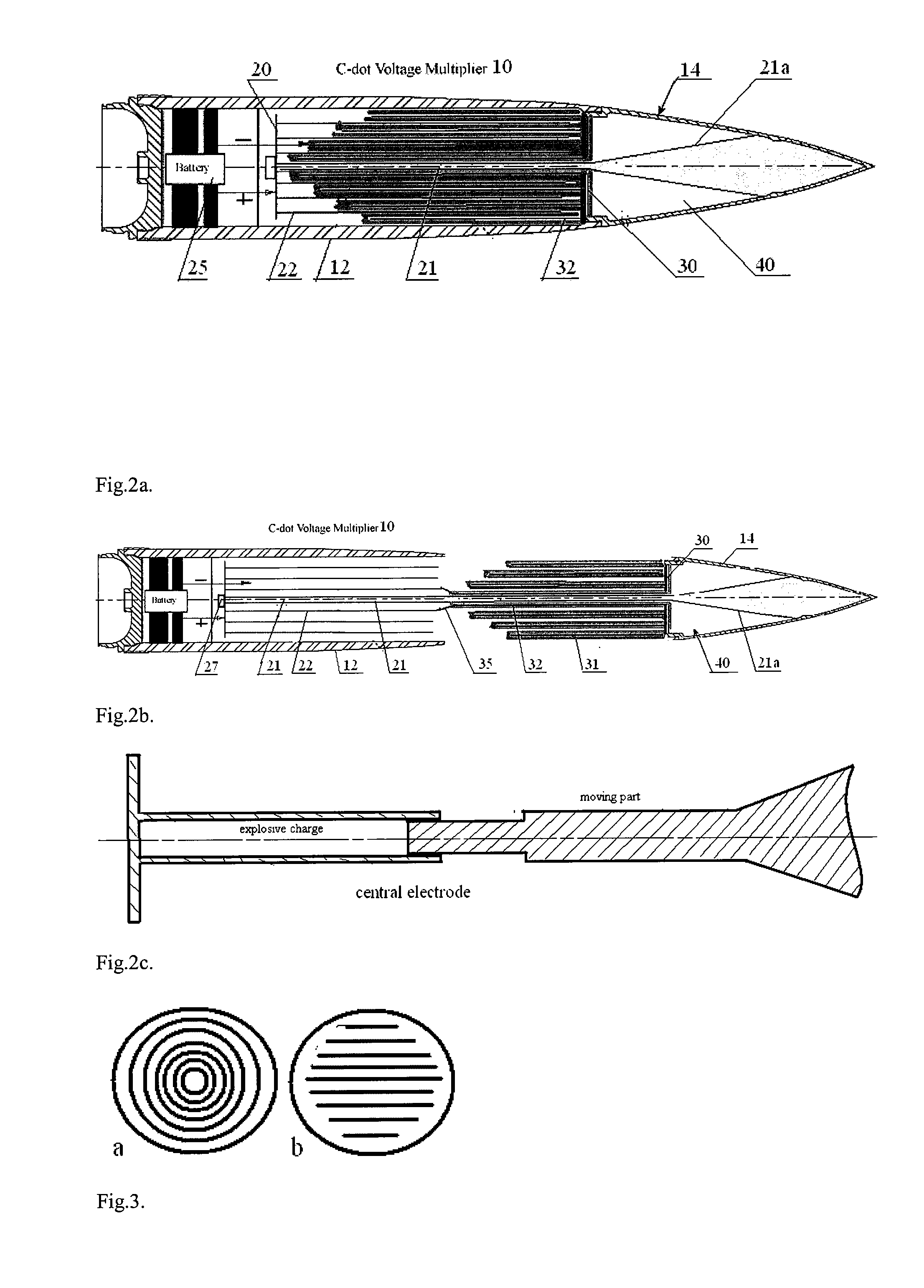
[0073]As an example, with reference to the capacitor configuration shown in FIG. 3, assume that the dielectric between the plates is Teflon or polyethylene with a dielectric constant ∈=2.1, the distance between plates d=2.5 mm and the dimension along cylinder axis l=100 mm. If the plates are wound so that the length of each plate is 2.8 m, the area of the plates is 0.28 m2 and the capacitance is equal to

C0=ɛAd∼2nF.

The electric field threshold for breakdown of polyethylene is about 60 kV / mm, so the 2.5-mm gap can support about 150 kV. Thus, for example, charging the capacitor to 1 kV and spooling the plates to reduce the capacitance by a factor of about 150 would give about 150 kV for switching out to a load.

[0074]The configurations of the capacitor plates can be different from the design shown in FIG. 6; one goal is to provide the maximal length for two parallel electrodes. In a munitions shell, for example, the capacitor can be charged up to U0=1.2 kV using an ordinary rectifier ...


PUM


Abstract

Systems and methods for generating high power, wideband microwave radiation pulses. A pulse generating device includes a capacitor as a primary electric energy store, a source of mechanical or chemical energy for modifying the capacitance of the capacitor, which then connects to a transmission line or pulse forming line (PFL) with many times increased electromagnetic energy, a switch and a broadband radiating element such as an antenna. A high voltage pulse and accordingly a high amount of electromagnetic energy is formed owing to decreasing the capacitance of an initially charged capacitor by dynamically changing a configuration of capacitor electrodes using mechanical work. The final configuration forms a transmission line, with the voltage and electric energy increased by the ratio of initial capacitance to final capacitance when the charge on the modifying capacitor is conserved. A switch connects opposite charged parts of the transmission line, and the resulting high voltage in the form of a pulse or multiple pulses propagates along the transmission line to a load (antenna) to generate one or more electromagnetic pulses.

Description

CROSS-REFERENCES TO RELATED APPLICATIONS[0001]This application claims the benefit of U.S. Provisional Application Ser. No. 60 / 869,533, filed Dec. 11, 2006, the entire disclosure of which is incorporated by reference for all purposes.BACKGROUND[0002]The present invention relates generally to electromagnetic munitions, and more particularly to systems and methods for generating electromagnetic pulses based on variable capacitance voltage multiplication.[0003]Electromagnetic munitions are typically designed to produce electromagnetic pulses capable of interacting with and disrupting or destroying electronic systems. A generated electromagnetic pulse typically couples through cables, ventilation grills, or gaps in target systems, producing overheating and burnout, punch-through or avalanche breakdown effects in semiconductors and electronics. Use of electromagnetic munitions in combat in respectable numbers would represent an important milestone in shifting warfare away from physically ...

Claims


Application Information

Patent Timeline
IPC IPC(8): H03K3/00H01G5/00
CPCF42B12/36F41H13/0093
Inventor FUKS, MIKHAILSCHAMILOGLU, EDLBENFORD, JAMES
Owner MICROWAVE SCI
Why Eureka
Try Eureka