

Anisotropic conductive film, method for producing the same, and bonded structure
a technology of anisotropic conductive film and conductive particle, applied in the direction of conductors, light beam reproducing, instruments, etc., can solve the problems of high conduction reliability, short circuit, and conductive particle movement along, and achieve excellent conduction reliability, easy bonding, and efficient production
- Summary
- Abstract
- Description
- Claims
- Application Information
AI Technical Summary
Benefits of technology
Problems solved by technology
Method used
Image

Examples
example 1
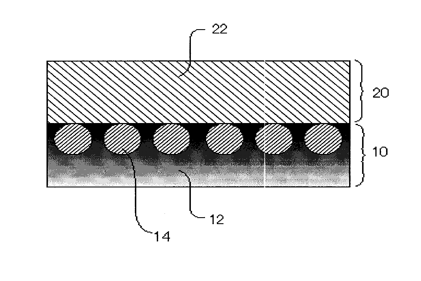
Production of Anisotropic Conductive Film
[0134]
[0135]A coating solution of a conductive particle-contained layer was prepared using the ingredients shown in Table 1 below.
TABLE 1ProportionIngredients(part(s) by mass)Acryl polymer(1604N, manufactured by70Soken Chemical & Engineering Co., Ltd.)Acryl monomer(3002A, manufactured by30Kyoeisha Chemical Co., Ltd.)Photopolymerization initiator(IRGANOX ®1369, manufactured by Chiba Japan K.K.)Thermoset initiator(PERHEXA 3M,4manufactured by NOF Corporation)Toluene100Total205
[0136]The thus obtained coating solution of a conductive particle-contained layer was applied onto a releasable PET sheet S1 using a bar coater, and dried at 60° C. for 10 minutes so as to evaporate the solvent contained therein, to thereby obtain a film A having a thickness of 10 μm (see FIG. 5A). The surface of the thus obtained film A had tackiness.
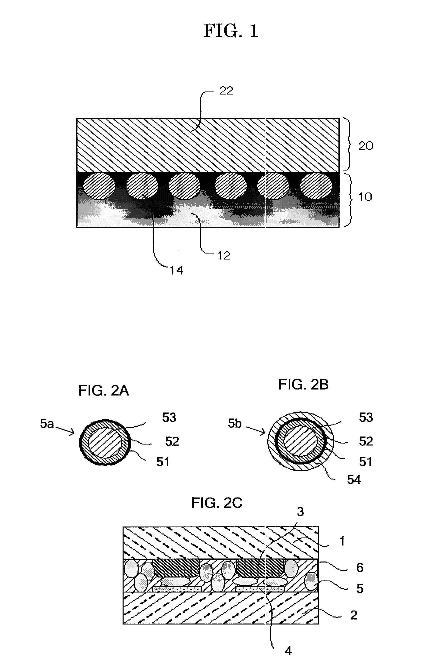
[0137]Subsequentially, 50 g of Ni—Au plating conductive particles P (BRIGHT GNR-EHLCD, manufactured by Nippon Chemical Indus...
example 2
Production of Anisotropic Conductive Film
[0145]An anisotropic conductive film was produced in the same manner as in Example 1, provided that the conductive particle-contained layer forming step was performed in the following manner.
[0146]A coating solution of a conductive particle-contained layer was prepared based upon the ingredients shown in Table 3.
TABLE 3ProportionIngredients(part(s) by mass)Bifunctional acryl monomer (CN112C60,70manufactured by Sartomer Company, Inc.)Phenoxy resin (PKHH, manufactured by30Union Carbide Corporation)Photopolymerization initiator (IRGACURE ®1369, manufactured by Chiba Japan K.K.)Thermoset initiator(organic peroxide)4(PERHEXA 3M, manufactured by NOF Corporation)Conductive particle(BRIGHT GNR-EHLCD,80diameter of 4 μm, manufactured by NipponChemical Industrial Co., Ltd.)Toluene100Total285
[0147]The thus obtained coating solution of a conductive particle-contained layer was applied onto a releasable PET sheet S6 using a bar coater, and dried in an oven...
example 3
[0150]An anisotropic conductive film was produced in the same manner as in Example 1, provided that the ingredients of a coating solution for the conductive particle-contained layer used in Example 1 was replaced with the ingredients shown in Table 4, and a carbon black was added to the ingredients as the curing light absorbent.
[0151]A coating solution for a conductive particle-contained layer was prepared based upon the ingredients shown in Table 4.
TABLE 4ProportionIngredients(part(s) by mass)Acryl polymer (PML103, manufactured by Soken55Chemical & Engineering Co., Ltd.)Acryl monomer45(M450, manufactured by Toagosei Co., Ltd.)Photopolymerization initiator (IRGANOX ®1369, manufactured by Chiba Japan K.K.)Thermoset initiator4(PERHEXA 3M, manufactured by NOF Corporation)Curing light absorbent (carbon black)1(Asahi-Thermal, manufactured by Asahi CarbonCo., Ltd., average particle size: 80 nm)Toluene100Total206
[0152]The thus obtained coating solution for EL conductive particle-contained ...
PUM
| Property | Measurement | Unit |
|---|---|---|
| thickness | aaaaa | aaaaa |
| thickness | aaaaa | aaaaa |
| thickness | aaaaa | aaaaa |
Abstract
Description
Claims
Application Information