
Electrolyte membrane for polymer electrolyte fuel cells, process for its production and membrane-electrode assembly for polymer electrolyte fuel cells

a technology of electrolyte fuel cells and electrolyte membranes, which is applied in the field of electrolyte membranes for process for its production and membrane electrolyte assembly of polymer electrolyte fuel cells, can solve the problems of reduced durability of fuel cells, mechanical strength of membranes tend to decrease, and low power generation performance, and achieve high proton conductivity , good dimensional stability, high power generation performan

Inactive Publication Date: 2009-09-24
ASAHI GLASS CO LTD
View PDF4 Cites 22 Cited by
  • Summary
  • Abstract
  • Description
  • Claims
  • Application Information

AI Technical Summary

Benefits of technology

[0019]The present invention has been made in view of such problems, and it is an object of the present invention to provide an electrolyte membrane for polymer electrolyte fuel cells having excellent dimensional stability even upon absorption of water, high proton conductivity and high power generation performance, with high productivity. Further, it is another object to provide a process for producing such an electrolyte membrane with high productivity. It is still another object to provide, at a low cost, a membrane-electrode assembly for polymer electrolyte fuel cells having a high output and excellent durability, as it has such an electrolyte membrane.
[0032]The electrolyte membrane for polymer electrolyte fuel cells of the present invention has good dimensional stability even upon absorption of water, high proton conductivity, high power generation performance and high productivity with a low cost.
[0033]According to the process for producing an electrolyte membrane for polymer electrolyte fuel cells of the present invention, it is possible to produce the electrolyte membrane of the present invention with high productivity.
[0034]The membrane-electrode assembly of the present invention provides a high output with a low cost and is excellent in durability.

Problems solved by technology

However, if the sulfonic group concentration is substantially increased, the mechanical strength of the membrane tends to decrease, or the membrane tends to be susceptible to creeping during the operation of the fuel cell for a long period of time, thus leading to a problem such as a decrease in the durability of the fuel cell.
On the other hand, if the membrane thickness is reduced, there will be a problem such that the mechanical strength of the membrane tends to be low, and in a case where a membrane-electrode assembly is to be prepared by bonding the membrane to a gas diffusion electrode, such processing tends to be difficult or the handling efficiency tends to be poor.
Further, upon absorption of water, the electrolyte membrane having a high sulfonic group concentration tends to show significantly large dimension change of membrane in plane, whereby various problems are likely to be brought about.
However, the porous material of PTFE is relatively soft from the nature of the material, whereby it is required to apply stretching operation at a high stretching rate and the method can hardly be said to be highly productive.
Further, Patent Document 2 proposes a method of filling an ion exchange resin to a porous material made of a polyolefin, but the chemical durability was inadequate, and there was a problem in the stability for a long period of time.
In the electrolyte membranes produced by these methods, the reinforcing materials themselves were not particularly positively entangled or bonded, whereby the reinforcing efficiency was poor, and it was necessary to incorporate a relatively large amount of such reinforcing materials.
In such a case, processing to a thin film tended to be difficult, and an increase in the membrane resistance was likely to be brought about.
Such a binder is an impurity for the electrolyte membrane for fuel cells, and the remaining binder may sometimes impair the durability of the fuel cells.
Further, in the method of processing the non-continuous short fibers by a method such as a paper making method, there will be a problem in making the membrane to be thin, such that with extremely thin fibers, handling is practically difficult.

Method used

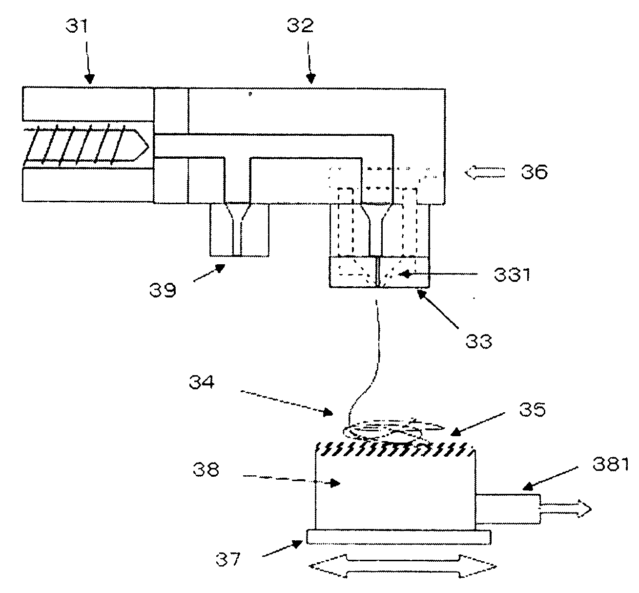
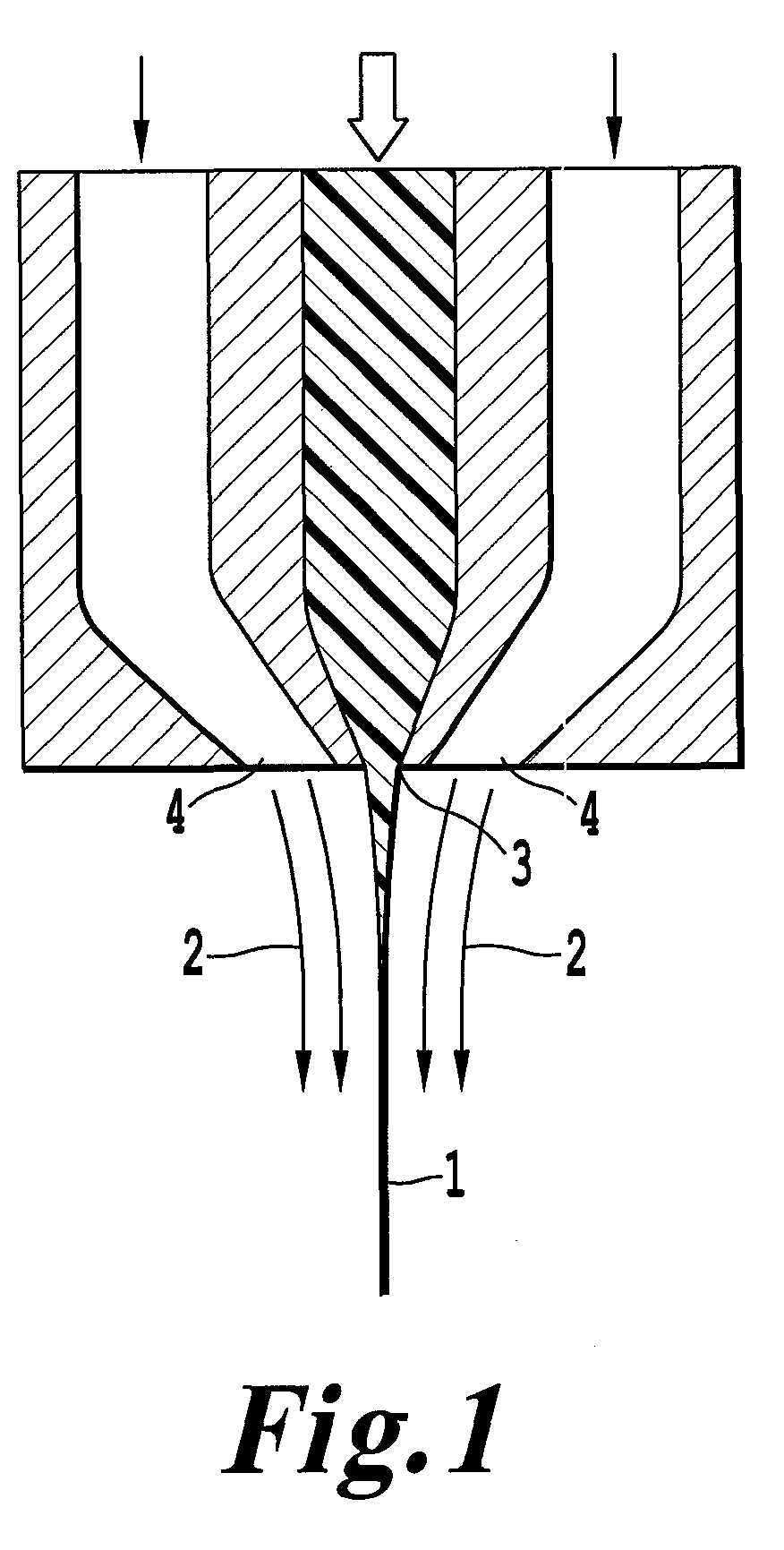
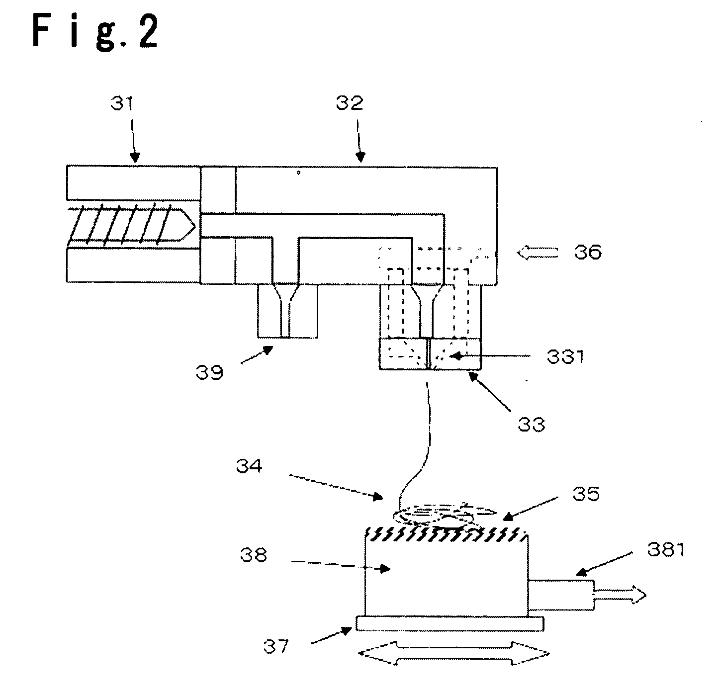

Image

  • Electrolyte membrane for polymer electrolyte fuel cells, process for its production and membrane-electrode assembly for polymer electrolyte fuel cells
  • Electrolyte membrane for polymer electrolyte fuel cells, process for its production and membrane-electrode assembly for polymer electrolyte fuel cells
  • Electrolyte membrane for polymer electrolyte fuel cells, process for its production and membrane-electrode assembly for polymer electrolyte fuel cells

Examples


example 1

Preparation Example 1

[0120](1) A polymerization tank having an internal capacity of 94 L and equipped with a stirrer, was deaerated and charged with 87.3 kg of 1,3-dichloro-1,1,2,2,3-pentafluoropropane (AK225cb, hereinafter referred to as “AK225cb”, manufactured by Asahi Glass Company, Limited) and 860 g of CH2═CH(CF2)4F. With stirring, the interior of the polymerization tank was heated to 66° C., and a mixed gas of TFE / E=89 / 11 (molar ratio) was introduced until the pressure in the polymerization tank became 1.4 MpaG. As a polymerization initiator, 667 g of a 1 mass % AK225cb solution of tert-butyl peroxypivalate was charged to initiate the polymerization.

[0121]A mixed gas having a composition of TFE / E=60 / 40 (molar ratio) and CH2═CH(CF2)4F in a ratio corresponding to 3.3 mol % to the mixed gas, were continuously charged so that the pressure became constant during the polymerization. Upon expiration of 8 hours after the initiation of the polymerization, when 7.1 kg of the monomer mix...

example 2

Preparation Example 2

[0136](1) Into a 430 L evacuated stainless steel autoclave, 164.8 kg of CF3(CF2)5H, 168.0 kg of AK-225cb, 337 kg of CH2═CH(CF2)4F and 89 kg of deionized water were charged, and the interior of the polymerization tank was heated to 65° C. with stirring, whereupon a mixed gas of TFE / E=89 / 11 (molar ratio) was introduced to 1.4 MPaG, and 40.1 g of a solution obtained by diluting an AK225cb solution of 50 mass % of tert-butyl peroxypivalate with CH2═CH(CF2)4F until tert-butyl peroxypivalate became 1 wt %, was charged to initiate the polymerization.

[0137]During the polymerization, a mixed gas of TFE / E=59 / 41 (molar ratio) and CH2═CH(CF2)4F in an amount corresponding to 3.3 mol % to the above mixed gas, were continuously added so that the pressure became 1.4 MPaG, and after charging 30 kg of a tetrafluoroethylene / ethylene mixed gas, the autoclave was cooled, and the residual gas was purged to complete the polymerization. The time required for the polymerization was 420 ...


PUM

PropertyMeasurementUnit
melting pointaaaaaaaaaa
diameteraaaaaaaaaa
thicknessaaaaaaaaaa

Abstract

To provide an electrolyte membrane having excellent dimensional stability even upon absorption of water, a high proton conductance and high power generation performance; and a process for producing the electrolyte membrane with a high productivity.An electrolyte membrane for polymer electrolyte fuel cells, which is made mainly of an ion exchange resin and reinforced with a nonwoven fabric made of fiber of a fluororesin wherein at least some of intersecting points of the fiber are fixed, and which has, as the outermost layer on one side or each side, a layer not reinforced, made of an ion exchange resin which may be the same as or different from the above ion exchange resin, wherein the fluororesin is an ethylene / tetrafluoroethylene copolymer having a melting point of at most 240° C., and the above fixing is fixing by fusion of the fiber.

Description

BACKGROUND OF THE INVENTION[0001]1. Field of the Invention[0002]The present invention relates to an electrolyte membrane for polymer electrolyte fuel cells, reinforced with a nonwoven fabric, a process for its production and a membrane-electrode assembly for polymer electrolyte fuel cells, having the electrolyte membrane.[0003]2. Discussion of Background[0004]In recent years, researches have been in progress for polymer electrolyte fuel cells employing a proton-conductive polymer membrane as an electrolyte membrane. Such polymer electrolyte fuel cells have characteristics such that they are operable at a low temperature, provide a high output density and can be small-sized, and thus, they are expected to be prospective in their use as e.g. power sources for vehicles.[0005]As an electrolyte membrane for polymer electrolyte fuel cells, a proton conductive ion exchange membrane having a thickness of from 10 to 200 μm is commonly used. Particularly, a cation exchange membrane made of a ...

Claims


Application Information

Patent Timeline
Patent Type & Authority Applications(United States)
IPC IPC(8): H01M8/10H01M8/14
CPCH01M8/1018H01M8/1044H01M8/1053H01M8/106H01M8/1062Y10T428/269H01M8/1083Y02E60/521Y10T428/2973Y10T428/2913Y10T428/26H01M8/1067Y02E60/50Y10T428/3154Y02P70/50
Inventor KOTERA, SEIGOWATABE, HIROYUKIAIDA, SHIGERU
Owner ASAHI GLASS CO LTD
Learn More