Carbon-Polymer Electrochemical Systems and Methods of Fabricating Them Using Layer-by-Layer Technology

a technology layers, applied in the field of carbon-polymer electrochemical systems, can solve the problems of fuel cell voltage outputs that are less than ideal, decrease with increasing load, and increase in recent applications

Active Publication Date: 2009-10-29
MASSACHUSETTS INST OF TECH
View PDF13 Cites 10 Cited by
  • Summary
  • Abstract
  • Description
  • Claims
  • Application Information

AI Technical Summary

Problems solved by technology

Early electrochemistry relied exclusively on liquid electrolytes, but recent applications are more demanding.
Fuel cells produce voltage outputs that are less than ideal and decrease with increasing load (current density).
Such decreased output is in part due to the ohmic losses within the fuel cell, including electronic impedances through the electrodes, contacts and current collectors.
Most authors use expensive lithographic and sputtering techniques to fabricate a large number of microelectrodes on a flat substrate and use conventional PEMs as separators.
However, it should be noted that the polyphosphazenes and the zirconia-polymer gels are not commercially available and the PBIs are relatively expensive.
Unfortunately, LBL conducting polymer films are weak ionic conductors, not stable and degrade in a sever electrochemical environment.

Method used


Image

  • Carbon-Polymer Electrochemical Systems and Methods of Fabricating Them Using Layer-by-Layer Technology
  • Carbon-Polymer Electrochemical Systems and Methods of Fabricating Them Using Layer-by-Layer Technology
  • Carbon-Polymer Electrochemical Systems and Methods of Fabricating Them Using Layer-by-Layer Technology

Examples


example 1

Membrane Preparation

[0204]All polyelectrolytes used to fabricate the LBL films were used as received. Poly(styrene sulfonic acid, sodium salt) [PSS; MW=70,000], Poly(diallyldimethyl ammonium chloride) [PDAC; MW=240,000], Linear Poly(ethyleneimine) [LPEI; MW=25,000], Poly(acrylic acid) [PAA; MW=90,000], Poly(styrenesulfonic acid-maleic acid, sodium salt) [PSSM3:1; MW=20,000], Poly(ethylene oxide) [PEO; MW=4,000,000], Poly(methylacrylic acid) [PMAA; MW=100,000], Poly(acrylic-co-acrylamide acid, sodium salt) [PAAcoAAm, MW=10,000,000 40% carboxy], all from Polysciences Inc. Poly(2-acrylamido-2-methyl-1-propane sulfonic acid) [PAMPS; MW=2,000,000], Poly(dimethylamine-co-epichlorohydrin) [PDME], and Polyaniline (Emarlidine base) [PAN, MW=100,000], from Aldrich. Nafion117 as a 5% resin solution from Fluka. Sodium chloride from Mallinckrodt C.P., Sulfuric acid 98%, Nitric acid 96.6%, 30% hydrogen peroxide from Fischer.

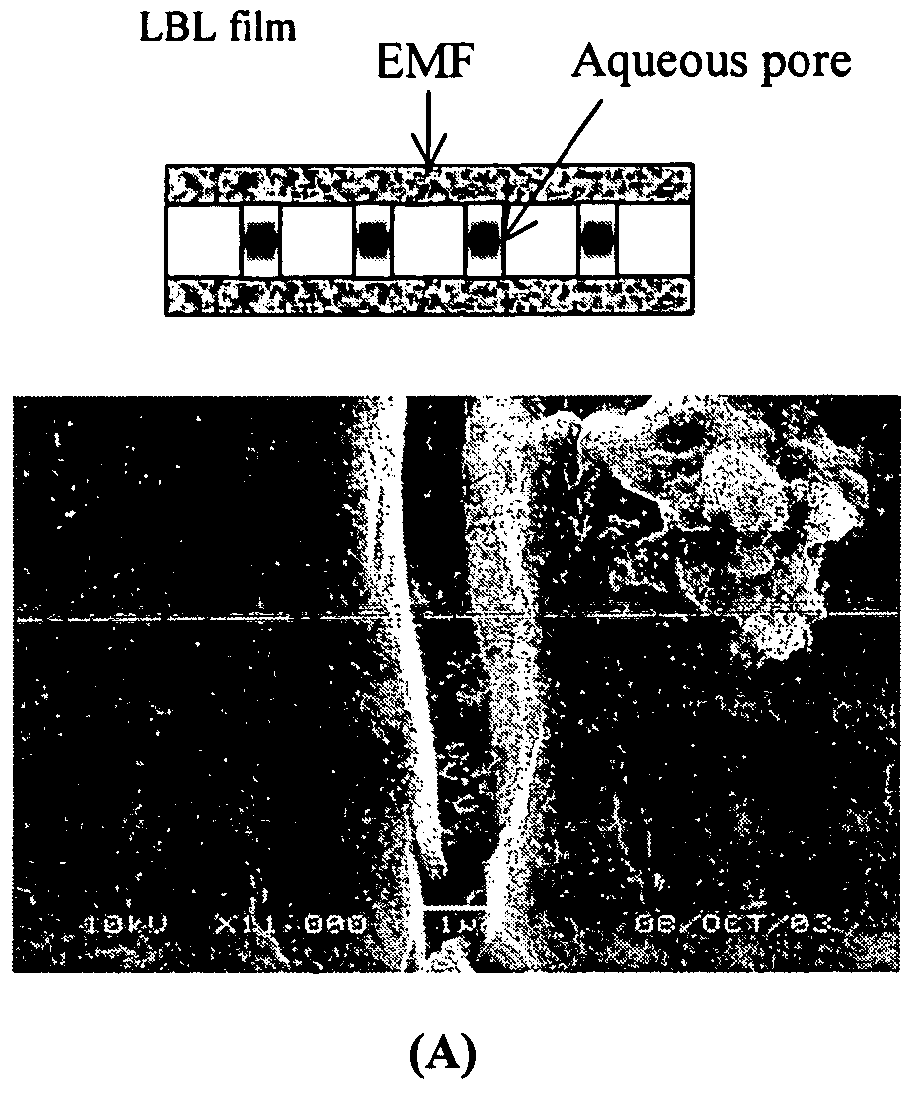
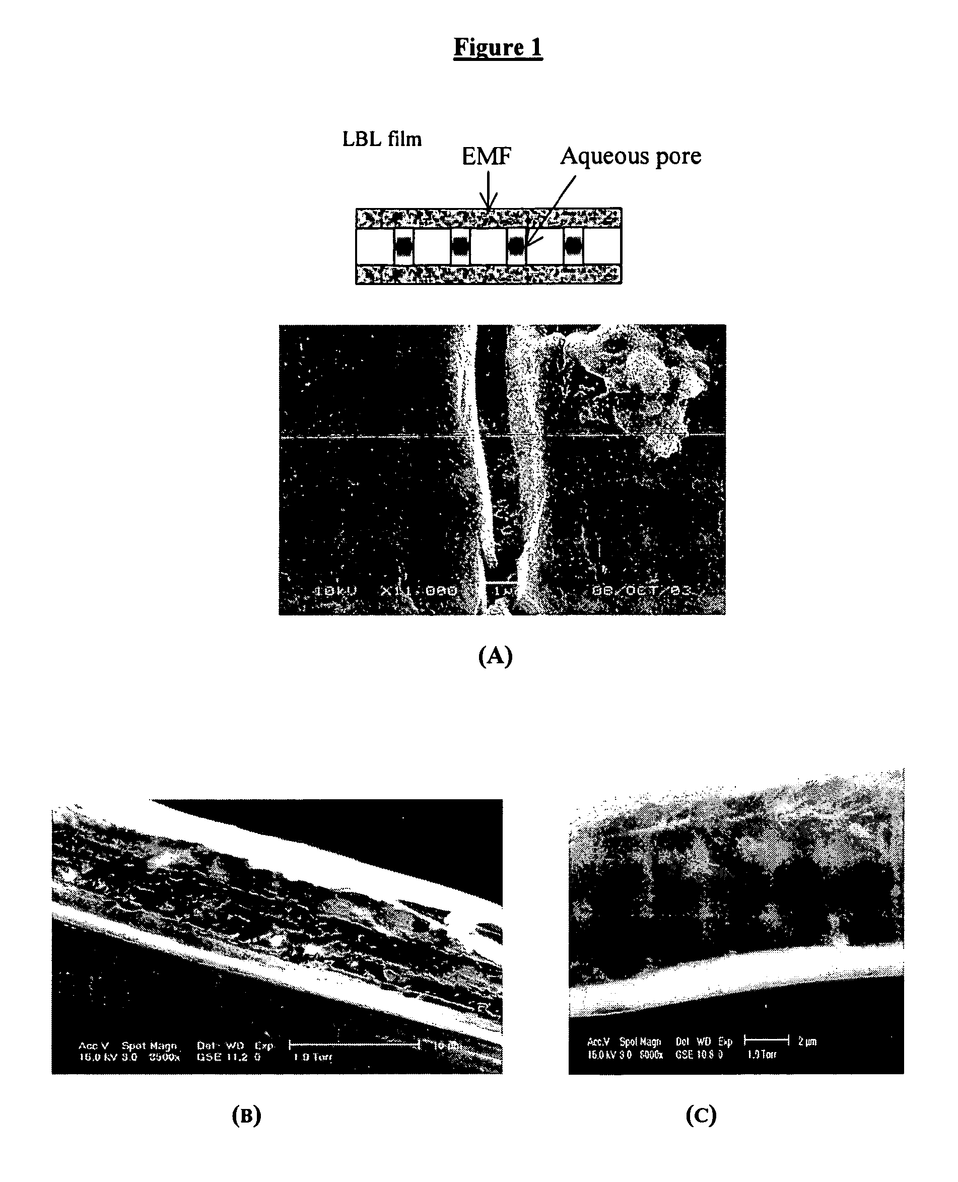
[0205]Nucleopore® membranes (25 mm diameter) were from SPI supplies. Nafi...

example 2

Fuel Cell Assembly

[0207]The “composite membranes” were soaked in 20.0 mM sulfuric acid solution for 20 minutes then placed on permanox slides ready to be folded between the ELAT C / Pt electrodes. All the “composite membranes”, including the Nafion112, were moderately hand pressed to the electrodes at room temperature. The untreated electrodes were twice soaked in 2.5% Nafion117 solution for 15 minutes and oven dried at 90° C. for 3 minutes.

[0208]The Nafion112® was pretreated by heating at 80° C. with 2% H2O2 solution for 2 hours followed by rinsing with Milli-Q pure water. The Nafion membrane was then soaked in a 0.5M sulfuric acid solution for two days and then boiled in 20 mM sulfuric acid solution for 1 hour before storing in pH=1.7H2SO4 solution. Slade, S.; Campbell, S. A.; Ralph, T. R.; Walsh, F. C. J. Electrochem. Soc. 2002, 149, A1556-A1564.

[0209]The MEA was fitted inside a fuel cell module that acts as bipolar plates but with no serpentine channels that provide intimate fuel ...


PUM

PropertyMeasurementUnit
thicknessaaaaaaaaaa
humidityaaaaaaaaaa
Areaaaaaaaaaaa

Abstract

One aspect of the invention provides ion-exchange and gas-diffusion membranes, fabricated by a layer-by-layer approach, for use, e.g., in electrochemical cells; a process for making membrane electrode assemblies fabricated using porous frameworks, LBL composite membranes and LBL carbon-Polymer electrodes; and the application of the membrane and electrode assemblies to a variety of devices, both electrochemical and otherwise.

Description

GOVERNMENT SUPPORT[0001]This invention was made with support from the National Science Foundation (grant number CTS-0136029); therefore, the government has certain rights in the invention.BACKGROUND OF THE INVENTION[0002]Electrochemical cells in which a chemical reaction is forced by adding electrical energy are called electrolytic cells. Central to the operation of any cell is the occurrence of oxidation and reduction reactions which produce or consume electrons. These reactions take place at electrode / solution interfaces, where the electrodes must be good electronic conductors. In operation, a cell is connected to an external load or to an external voltage source, and electric charge is transferred by electrons between the anode and the cathode through the external circuit. To complete the electric circuit through the cell an additional mechanism must exist for internal charge transfer. This is provided by one or more electrolytes, which support charge transfer by ionic conduction...

Claims


Application Information

Patent Timeline
Patent Type & Authority Applications(United States)
IPC IPC(8): H01M2/16B01D67/00H01M50/414H01M50/42H01M50/423H01M50/489H01M50/497
CPCB01D69/02Y02E60/521B01D69/122B01D69/141B01D71/28B01D71/40B01D71/44B01D71/60B01D71/82C25B13/04H01M2/1653H01M2/1673H01M4/8605H01M4/92H01M4/926H01M8/1004H01M8/1023H01M8/103H01M8/1039H01M8/1046H01M8/1048H01M8/1051H01M8/1053B01D69/12Y10T428/31504Y10T428/31855Y02P70/50Y02E60/50Y02E60/10H01M50/46H01M50/414H01M50/489H01M50/42H01M50/423H01M50/497
Inventor HAMMOND-CUNNINGHAM, PAULA T.FARHAT, TAREK R.
Owner MASSACHUSETTS INST OF TECH
Why Eureka
Try Eureka