Method for Separating and Enriching Isotope Material, Multistage Rotor, and Apparatus for Separating and Enriching Isotope Material

a technology of isotope material and multi-stage rotor, which is applied in the direction of sedimentation separation, solid-state diffusion coating, centrifugal force sedimentation separation, etc., can solve the problems of corrosive gas, inefficient methods, and hardly used in industrial manufacturing, and achieve cost reduction

Inactive Publication Date: 2009-11-05
NAT UNIV CORP KUMAMOTO UNIV +1
View PDF7 Cites 9 Cited by
  • Summary
  • Abstract
  • Description
  • Claims
  • Application Information

AI Technical Summary

Benefits of technology

[0075]Because it is unnecessary to use corrosive gas, high-safety, economic efficiency with compact facilities, further development of unique techniques and

Problems solved by technology

As other methods, there are the electromagnetic method, the laser method, the nozzle separation method, the thermal diffusion method, the cryogenic method, the plasma method, and the chemical exchange method, but these methods are inefficient, and are hardly used in the industrial manufacturing except the case of enrichment for small amounts of particular kinds of isotopes.
In this method, corrosive gas, low separation coefficient, and high-cost caused by the large-scale facilities are pointed out as issues.

Method used


Image

  • Method for Separating and Enriching Isotope Material, Multistage Rotor, and Apparatus for Separating and Enriching Isotope Material
  • Method for Separating and Enriching Isotope Material, Multistage Rotor, and Apparatus for Separating and Enriching Isotope Material
  • Method for Separating and Enriching Isotope Material, Multistage Rotor, and Apparatus for Separating and Enriching Isotope Material

Examples


example 1

Simple Substance: Simple Se: Liquid and Solid

[0159]As an example that the material to be processed was a single metal, the case where single selenium (Se) was used was introduced. Natural Se was composed of isotopes such as Se (0.9%), Se (9.0%), Se (7.6%), Se (23.5%), Se (49.7%), Se (9.2%) and the like.

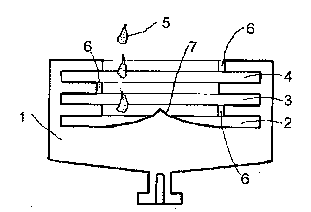
[0160]As a starting sample, grain sample of 4N—Se (meaning Se with a purity of 99.99%) was dissolved and solidified in a glass tube with an inner diameter of 5 mm under argon atmosphere, and the starting sample was cut as a cylindrical sample with a diameter of 5 mm and a length of 5 mm. A capsule of SUS304 with an inner diameter of 5 mm was filled with this, and the resultant was loaded on a rotor of Ti based alloy with a diameter of 80 mm (refer to FIG. 4).

[0161]In the experiment, an air-turbine type supercentrifuge in Japan Atomic Energy Agency, capable of generating a gravity field of 1,000,000 G (1 G=9.8 m / s2) or more over a long time at a high temperature was used. Two types of ...

example 2

Solid Solution: Se—Te Alloy

[0172]As an example that the material to be processed was a solid solution, the case where selenium (Se)-tellurium (Te) alloy was used was introduced. As a starting sample, grain sample of 4N—Se, and 4N—Te (99.99%) was dissolved and solidified in a glass tube with an inner diameter of 4 mm under argon atmosphere, and the starting sample was cut as a cylindrical sample with a diameter of 4 mm and a length of 5 mm. A capsule of SUS304 with an inner diameter of 4 mm was filled with this.

[0173]In the experiment, an air-turbine type supercentrifuge in Japan Atomic Energy Agency, capable of generating a gravity field of 1,000,000 G (1 G=9.8 m / s2) or more for a long time at a high temperature was used. The experimental temperature was set at 260° C., and the experimental time was 100 hours. The analysis of the isotopes was performed by Institute for Study of the Earth's Interior, Okayama University which was located in Mitomo, Okayama Prefecture by using Cameca i...

example 3

Halides: Super-Ionic Conductor: Silver Iodide (AgI)

[0176]As an example that the material to be processed was a halide and super-ionic conductor, the case where silver iodide (AgI) was used was introduced (experiments 1, 2, and 3). Silver iodide (AgI) had a phase transition point from β-AgI to α-AgI at 148° C. α-AgI was a super-ionic conductor with a very-large diffusion coefficient (approximately 10−3 cm2 / s) of silver ion. The experimental temperature was set at 148° C. or more, and α-AgI was placed under the strong centrifugal acceleration field so that high-speed sedimentation phenomenon of Ag atoms in α-AgI might be expected. The experiment was conducted in consideration that the experimental temperature was set at 148° C. or less before removing the gravity so that the sample with the fixed isotope abundance ratio might be collected. The melting point was 555° C. In the experiment, an air-turbine type supercentrifuge in Japan Atomic Energy Agency, capable of generating a gravity...


PUM

PropertyMeasurementUnit
Angleaaaaaaaaaa
Magnetic fieldaaaaaaaaaa
Speedaaaaaaaaaa

Abstract

This invention provides a method for separating and enriching isotopes in an efficient and low-cost manner from a condensation-system (liquid or/and solid) material comprising two or more different isotopes by taking advantage of the sedimentation of atoms through an acceleration field by ultra-high speed rotation. A condensation-system (liquid or/and solid) material (5) comprising the two or more isotopes is placed in a sedimentation tank (for example, 2) which is then housed in a supercentrifuge. The supercentrifuge in its rotor is rotation driven by an ultra-high speed rotation power source, and an acceleration field of energy of 100000 G to 1500000 G, i.e., about 100 to 800 m/s in terms of peripheral velocity, is applied to the above condensed (liquid or/and solid) material under such a temperature that is specified by an isotope material to be enriched. In this case, a difference in centrifugal force applied is provided between the isotopes in the condensed (liquid or/and solid) material comprising the at least two isotopes. By virtue of sedimentation by taking advantage of this difference, isotope atoms within the condensed material interact, and, consequently, separation and enrichment of the isotopes can be realized in a higher efficiency than the case where gas is used, by conducting the separation and enrichment of the isotopes within the liquid material, using an effective material, and using a multistaged rotor system.

Description

TECHNICAL FIELD[0001]The present invention relates to a method of separating and enriching isotopes through diffusion process from condensed material containing two or more different isotopes by using sedimentation of atoms through an acceleration field (a gravity field and a centrifugal field) by ultra-high speed rotation and an apparatus for separating and enriching, and a multistage rotor applied to the method in operation.BACKGROUND ART[0002]Here, the acceleration field is physically the same as the gravity field, and because the acceleration field in the present invention is generated by a centrifugal force, it may be referred to as a centrifugal field or a centrifugal acceleration field. Also, a strong (high) acceleration field is referred to as a high acceleration field, a high-gravity field, a supergravity field, or a supercentrifugal field.[0003]Due to the energy situation and the highly-developed communication industry in recent years, the importance of isotopes such as en...

Claims


Application Information

Patent Timeline
IPC IPC(8): B01D59/20B01D59/50
CPCB01D59/20C22F3/00C23C26/00C23C10/28C23C10/18Y10S494/90
Inventor MASHIMO, TSUTOMUONO, MASAOHUANG, XINSHENGIGUCHI, YUSUKEOKAYASU, SATORUYASUOKA, HIROSHISHIBASAKI, KOJISUEYOSHI, MASANORI
Owner NAT UNIV CORP KUMAMOTO UNIV
Why Eureka
Try Eureka