

Adhesive composition for optical filter, optical filter and display device
a technology of optical filters and adhesive compositions, applied in the direction of film/foil adhesives, lighting and heating apparatus, instruments, etc., can solve the problems of easy deterioration of ultraviolet light, inability to obtain vivid red color, and malfunction of peripheral devices, so as to reduce the cost of production process, prevent discoloration of electroconductive mesh surfaces, and simplify production process
- Summary
- Abstract
- Description
- Claims
- Application Information
AI Technical Summary
Benefits of technology
Problems solved by technology
Method used
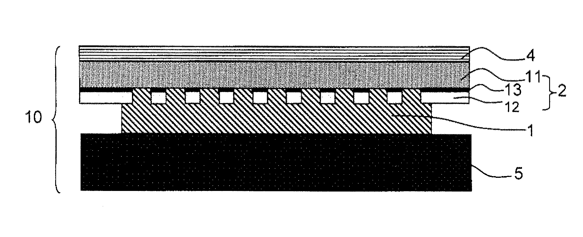
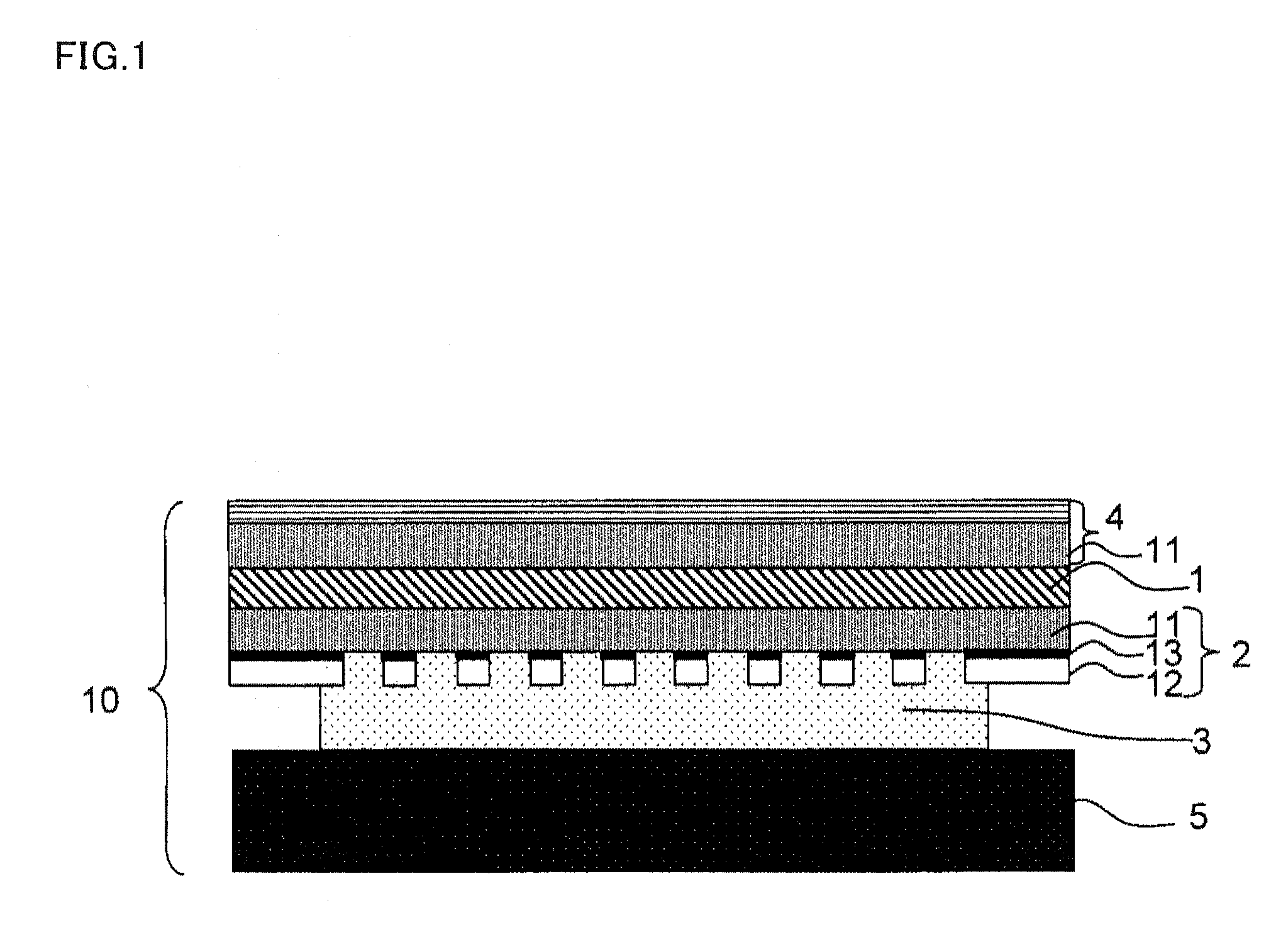
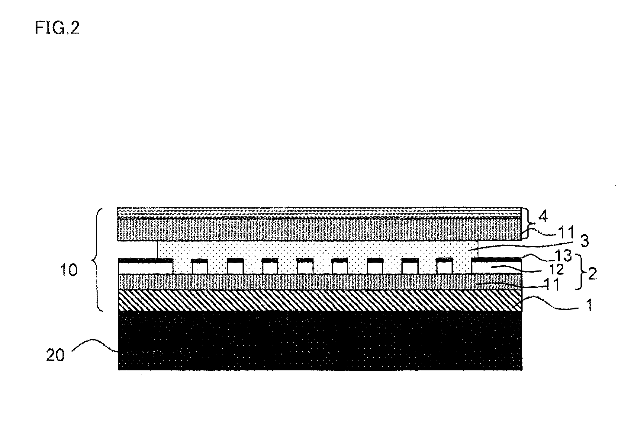
Image

Examples
example 1
[0352]As solvents, 25 parts by weight of toluene and 25 parts by weight of methyl ethyl ketone were mixed with 50 parts by weight of a triblock copolymer (product name: LA2140e, manufactured by Kuraray Co., Ltd.) with a (polymethyl methacrylate)-(poly-n-butyl acrylate)-(polymethyl methacrylate) structure having a weight average molecular weight of 80,000 and a molecular weight distribution (Mw / Mn) of 1.17, to prepare a resin solution (s-I).
[0353]As a solvent, 50 parts by weight of methyl ethyl ketone was mixed with 50 parts by weight of polymethyl methacrylate having a weight average molecular weight of 15,000 and the glass transition temperature of 102° C., to prepare a resin solution (s-II).
[0354]Further, 0.2 parts by weight of Excolor IR12 (a phthalocyanine-based compound) and 0.1 parts by weight of IR14 (a phthalocyanine-based compound) (both of which are product names, manufactured by Nippon Shokubai Co., Ltd.), 0.4 parts by weight of KayasorbIRG-068 (product name, manufactured...
example 2
[0370]An adhesive composition was prepared in the same manner as in Example 1 except for using isobornyl polymethacrylate having a weight average molecular weight of 70,000 and a glass transition temperature of 112° C. in place of polymethyl methacrylate having a weight average molecular weight of 15,000 and a glass transition temperature of 102° C. and an adhesive layer having optical filter functions was obtained in the same manner as in Example 1.
[0371]The adhesive layer of Example 2 was evaluated for its durability, glass adhesion and haze by the same evaluation method as in Example 1. The result is shown in Table 1.
example 3
[0372]An adhesive composition was prepared in the same manner as in Example 1 except for using isobornyl polymethacrylate having a weight average molecular weight of 100,000 and a glass transition temperature of 112° C. in place of polymethyl methacrylate having a weight average molecular weight of 15,000 and a glass transition temperature of 102° C. and an adhesive layer having optical filter functions was obtained in the same manner as in Example 1.
[0373]The adhesive layer of Example 3 was evaluated for its durability, glass adhesion and haze by the same evaluation method as in Example 1. The result is shown in Table 1.
PUM
| Property | Measurement | Unit |
|---|---|---|
| molecular weight distribution | aaaaa | aaaaa |
| temperature | aaaaa | aaaaa |
| wavelength | aaaaa | aaaaa |
Abstract
Description
Claims
Application Information