Methods of fabricating environmental barrier coatings for silicon based substrates

a technology of environmental barrier coating and substrate, which is applied in the direction of coatings, mechanical equipment, machines/engines, etc., can solve the problems of significant surface recession and mass loss of silicon-bearing materials, unacceptably high recession rate, and plasma spray process can have several limitations

Inactive Publication Date: 2009-12-03
GENERAL ELECTRIC CO
View PDF13 Cites 82 Cited by
  • Summary
  • Abstract
  • Description
  • Claims
  • Application Information

AI Technical Summary

Benefits of technology

[0007]Disclosed herein are methods of fabricating an environmental barrier coating on a silicon-based substrate. In one embodiment the method includes protecting an article from a high temperature environment by providing a substrate comprising silicon, forming a slurry coating composition, wherein the composition comprises a metallic silicon powder, a rare-earth oxide, an alkaline earth metal oxide, an aluminum oxide, or a combination comprising at least one of the foregoing, and a binder effective to chemically stabilize the slurry coating, applying a layer of the slurry coating over the substrate, and heat-treating the slurry coating under conditions sufficient to oxidize the metallic silicon powder and form an alkaline earth metal aluminosilicate, a rare-earth silicate, an aluminum silicate, or a combination comprising at least one of the foregoing bonded to the substrate.
[0008]In another embodiment, a method of fabricating an environmental barrier coating on a substrate includes providing the substrate, wherein the substrate comprises silicon; forming a water based slurry coating composition, wherein the composition comprises a metallic silicon powder, a rare-earth oxide, an alkaline earth metal oxide, an aluminum oxide, or a combination comprising at least one of the foregoing, and a binder effective to chemically stabilize the slurry coating; disposing a bond layer over the substrate, wherein the bond layer comprises a silicon metal; disposing a layer of the slurry coating over the bond layer; and heat-treating the slurry coating under conditions sufficient to oxidize the metallic silicon powder and form an alkaline earth metal aluminosilicate, a rare-earth silicate, an aluminum silicate, or a combination comprising at least one of the foregoing bonded to the substrate.

Problems solved by technology

However, the environment, to which these applications are exposed often contain water vapor, which at high temperatures is known to cause significant surface recession and mass loss in silicon-bearing materials.
The water vapor reacts with the structural material at high temperatures to form volatile silicon-containing species, often resulting in unacceptably high recession rates.
A plasma spray process can have several limitations and disadvantages particular to EBC applications and requirements.
A particular limitation is that plasma spraying is a line-of-sight process, thereby limiting the utility of the technique to substrates with simple geometries, or substrates only requiring a coating on the external features.
Achieving a hermetic, gas-tight ceramic coating microstructure using plasma spray deposition is very difficult because the coating microstructure includes a variety of open defects, such as micro-cracks, macro-cracks, interlayer gaps, interlamellar gaps, and the like, that are inherent to the plasma spray deposition process.
Another limitation of plasma spraying EBC is that the coating materials deposited by the method are prone to undesirable changes in chemistry and structure owing to intense heating of the particles in the plasma plume, as well as to the rapid quenching of the molten particles on a substrate.
Upon exposure to high temperature, transformation toward the equilibrium state occurs, and the constrained coating can undergo a variety of dimensional changes resulting in stresses in the coating that can lead to various types of cracking behavior.
Additionally, the coatings processed by plasma spraying are prone to contain open porosity and / or a network of fine cracks intercepting the otherwise closed pores and voids.
For EBC applications open porosity in the coating can be detrimental.
The open porosity provides a path for rapid water vapor penetration and, hence, accelerated localized degradation and / or deterioration of the underlying materials making them prone to environmental attacks such as water vapor mediated oxidation and volatilization.

Method used


Image

  • Methods of fabricating environmental barrier coatings for silicon based substrates
  • Methods of fabricating environmental barrier coatings for silicon based substrates
  • Methods of fabricating environmental barrier coatings for silicon based substrates

Examples


example 1

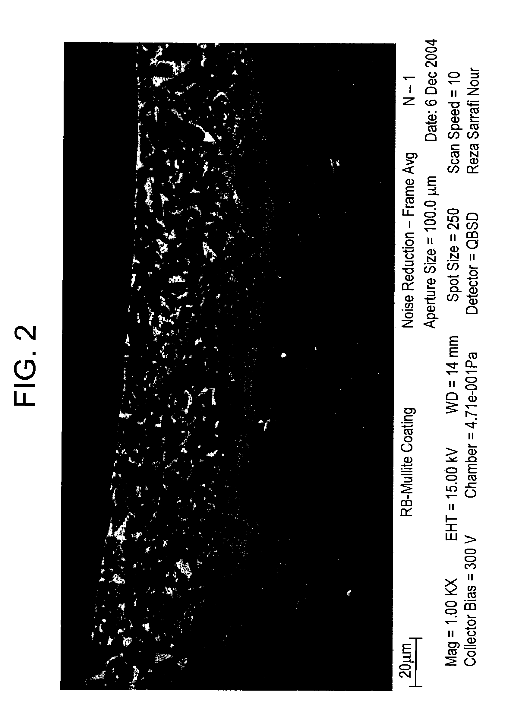
[0033]The method described herein was evaluated by reaction bonding mullite (RBM) to a ceramic matrix composite substrate comprising a silicon carbide reinforced with fibers comprising silicon carbide (SiC—SiC CMC). A slurry was prepared by mixing 2.55 moles (M) of a metallic silicon powder, 1.85 M aluminum oxide (Al2O3), 0.15 M RE2O3 (wherein the rare earth oxide can be selected to be yttrium oxide, ytterbium oxide, and / or lutetium oxide) together with 40 to 60 percent by total weight (wt. %) water, 1 to 2 wt. % colloidal silica as binder, and 0.1 to 1 wt. % Octanol® as a de-foaming agent. The solid and liquid constituents were mixed in a plastic container on a standard bench-top paint shaker for about 15 minutes using 2 millimeter (mm) diameter milling media. Upon complete mixing, the Octanol was added to the resulting slurry and the slurry was stirred further for homogenization. Colloidal silica was used as a binder and was 30% (w / w) in water. The colloidal silica was LP30, manuf...


PUM

PropertyMeasurementUnit
temperatureaaaaaaaaaa
shrinkageaaaaaaaaaa
thicknessaaaaaaaaaa

Abstract

A method of protecting an article from a high temperature environment, the method includes providing a substrate comprising silicon, forming a slurry coating composition, wherein the composition comprises a metallic silicon powder, a rare-earth oxide, an alkaline earth metal oxide, an aluminum oxide, or a combination comprising at least one of the foregoing, and a binder effective to chemically stabilize the slurry coating, applying a layer of the slurry coating over the substrate, and heat-treating the slurry coating under conditions sufficient to oxidize the metallic silicon powder and form an alkaline earth metal aluminosilicate, a rare-earth silicate, an aluminum silicate, or a combination comprising at least one of the foregoing bonded to the substrate.

Description

GOVERNMENT RIGHTS[0001]This invention was made with Government support under Government contract No. DE-FC26-05NT42643 awarded by the Department of Energy. The Government has certain rights in this invention.BACKGROUND OF THE INVENTION[0002]The present disclosure relates generally to environmental barrier coatings for silicon based substrates, and more particularly, to methods of fabricating the environmental barrier coating systems for protecting substrates from exposure to high-temperature environments.[0003]Silicon-bearing materials, such as, for example, ceramics, alloys, and intermetallics, offer attractive properties for use in structures designed for service at high temperatures in such applications as gas turbine engines, heat exchangers, and internal combustion engines, for example. However, the environment, to which these applications are exposed often contain water vapor, which at high temperatures is known to cause significant surface recession and mass loss in silicon-b...

Claims


Application Information

Patent Timeline
Patent Type & Authority Applications(United States)
IPC IPC(8): B05D5/00B05D3/02B05D3/04
CPCC04B41/009F05D2300/222C04B41/52C04B41/87C04B41/89C23C24/08C23C26/00F01D5/288C04B41/5024F05D2300/2283C04B41/4539C04B41/455C04B41/5037C04B41/5096C04B35/565C04B35/584C04B35/806C04B35/58092
Inventor SARRAFI-NOUR, REZAKOOL, LAWRENCE BERNARD
Owner GENERAL ELECTRIC CO
Why Eureka
Try Eureka