Power generating apparatus

a power generation apparatus and power technology, applied in the direction of electrochemical generators, cell components, energy input, etc., can solve the problems of high temperature water heating of metal materials, large apparatus, heat damage, etc., to accelerate interfacial reaction, reduce polarization resistance, and prevent container explosion

Inactive Publication Date: 2009-12-31
TECH BANK CO LTD
View PDF2 Cites 11 Cited by
  • Summary
  • Abstract
  • Description
  • Claims
  • Application Information

AI Technical Summary

Benefits of technology

[0024]In addition, in this case of batteries which are not hermetically sealed, a nonwoven fabric and the like having a capillary function and a gel body may be used in combination and contained in the electrolysis solution in addition to the polymer solid electrolyte from necessity to impart the electrolyte with a function of shielding hydrogen gas outflow, thereby enabling to send hydrogen gas to a hydrogen demanding unit without allowing the hydrogen gas generated in the hydrogen generating container to flow out of the open area of the positive electrode to the outside and to prevent explosion of the container as well. This can be applied to the field of small-sized batteries for portable devices such as a tabular battery and a button battery.
[0025]In the meantime, when a hermetically sealed battery is to be formed, a battery element may be constructed so that active material such as a metal such as Ni and Ti, an alloy, a powder of a metal compound and a catalyst, which are capable of accepting respective ions of hydrogen and magnesium, are mixed and contained in the positive electrode, thereby enabling to accept a plural number of ions including a polyvalent ion by the battery element with an enlarged unit area and capable of accelerating interfacial reactions and to function as a battery with a reduced polarization resistance and serving as hydrolysis.
[0026]In addition, for example, ionization of magnesium (Mg) of the negative electrode may be increased or decreased by applying the electric power generated in the battery element of the container to a load device so that the amount of electric current which passes through the load device is changed, thereby enabling the amount of metal crystals changing to magnesium hydroxide from the surface of magnesium (Mg) to be proportional thereto. At this time, hydrogen atoms lose the settled site among crystals of Mg metal and each two of the atoms bind together to be a hydrogen molecule and thus hydrogen gas is generated. This produced amount depends on the reaction by the electric current through the load, and thus the generation of hydrogen gas can be also controlled by the electric current.
[0027]Besides, control of the hydrogen generation can be facilitated even in the field of fuel cell-powered automobiles where a hydrogen demanding device with a high voltage and with large variations in the hydrogen consumption is used by stacking the container or the cells of the battery element to construct a battery.

Problems solved by technology

The generation of hydrogen by heating a metal material at a high temperature is disadvantageous in that a large apparatus is necessary and heat damage occurs.
The generation of hydrogen by reacting a dry solid hydride containing an acidic or alkaline material with steam suffers from a problem of a deterioration in devices such as solid polymer fuel cells by the acid or alkali and a serious problem that the generation of hydrogen occurs at a low humidity even during the stop of operation.
Accordingly, water supplied for hydrolysis per se is vigorously evaporated, and a large amount of water should be supplied resulting in low hydrogen generation efficiency.
On the other hand, the generation of hydrogen by reacting a dry solid hydride containing an acidic or alkaline material with steam also has an additional drawback that the regeneration of the hydride is troublesome and, further, harmful substances are produced.
Further, in the conventional techniques, the control of the generated hydrogen gas is difficult, and any means for storing excess hydrogen gas is not provided.
This may cause explosion due to the pressure of the generated excess gas.
Accordingly, the conventional techniques are dangerous and unsuitable as a hydrogen supply source for industrially and commercially used hydrogen demanding units such as solid polymer fuel cells, hydrogen fueled engines, hydrogen welding / cutting systems, and semiconductor production apparatuses.
The problem with the control of hydrogen generation is particularly significant when apparatuses, particularly small mobile (cellular) telephones or automobiles, are used upside down, or when random hydrogen supply is required.
Since the water or solution always stays on a gravity acting side, difficulties are experienced in releasing the generated hydrogen gas, in ensuring flow passages for the generated hydrogen gas, and in performing control to cope with a fluctuation in a consumed hydrogen amount.

Method used


Image

  • Power generating apparatus
  • Power generating apparatus
  • Power generating apparatus

Examples


example 1

[0038]The step of reducing the particle size of a functional material, the step of hydrogenating the functional material, the step of forming a film, and the step of mounting the functional material will be described.

[0039]When the functional material is a hydrogen storage alloy, for example, calcium (Ca), lanthanum (La), magnesium (Mg), nickel (Ni), titanium (Ti), and third elements, for example, vanadium (V), are generally known as materials for the hydrogen storage alloy. These materials are mixed together, and the mixture is melted to produce cast hydrogen storage alloys such as La—Ni-base alloys and Mg—Ti-base alloys.

[0040]Hydrogen is occluded in these alloys, followed by initial pulverization or mechanical pulverization to produce a fine powder of a hydrogen storage material. An alternative method for producing a fine powder of a functional material is as follows. Particles of a metal or an alloy or particles of Mg are placed as a functional material in a pressure-resistant co...

example 2

[0050]Experimentation of hydrolysis and generation of electricity using magnesium (Mg) or magnesium hydride (MgH2) as a functional material will be described.

[0051]Experiments of a fastest self-propelled reaction of hydrolysis with aqueous solutions of naturally existing solutes were attempted. In the experiments, two types of samples were used. Sample 1: 1 g of magnesium (Mg) having a particle size of not less than 200 μm. Sample 2: 1 g of magnesium hydride (MgH2) having a particle size of not more than 50 μm.

[0052]Three types of aqueous solutions were used as the aqueous solution. Aqueous solution 1: water (H2O). Aqueous solution 2: an 8% aqueous citric acid (C6H8O7) solution. Aqueous solution 3: a 5% aqueous bittern (magnesium chloride hexahydrate MgCl2.6H2O) solution.

[0053]The experiment was started by pouring each 5 cc of the three types of aqueous solutions at room temperature (20° C.) to the samples in test tubes. When the self-propelled reaction rate is low, observation and ...

example 3

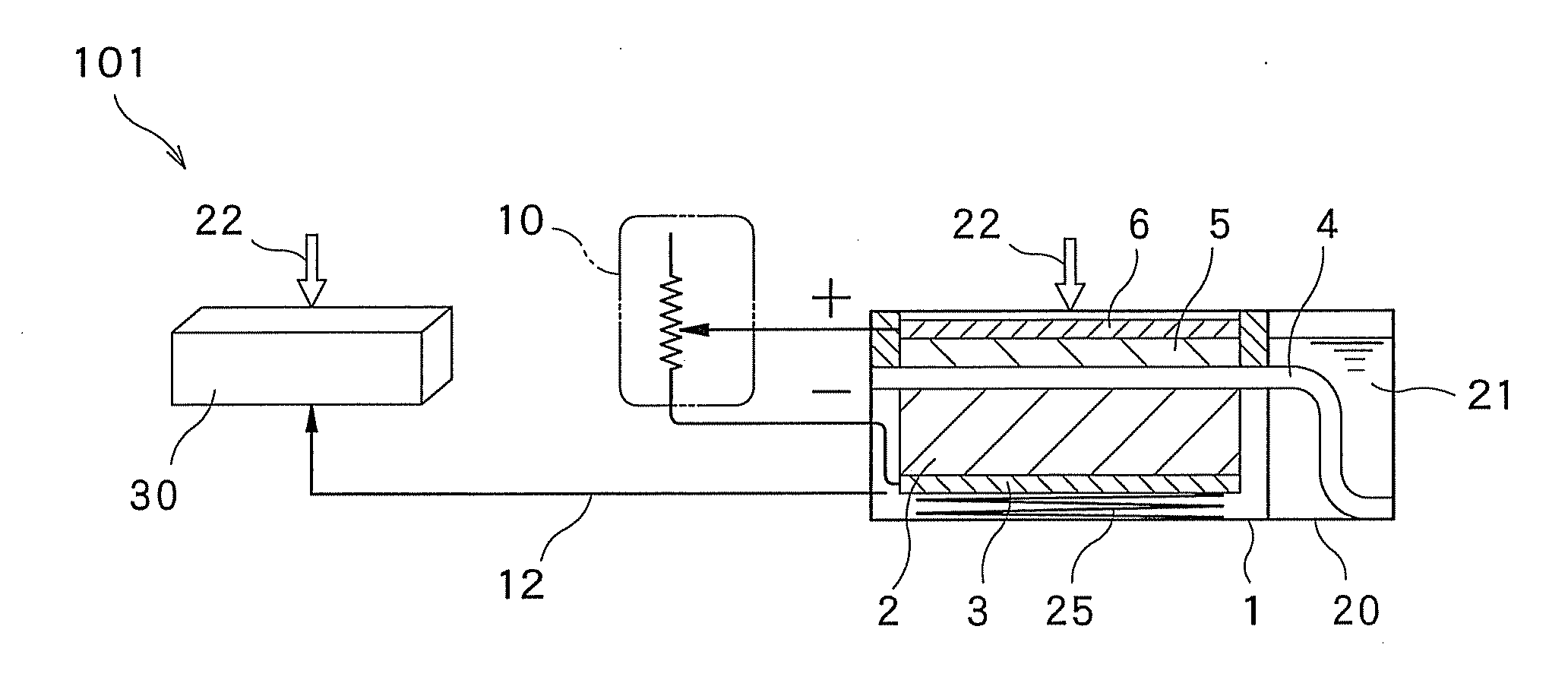
[0064]Embodiments of the present invention will be described with reference to FIGS. 1, 2 and 3. In FIG. 1, a positive electrode 6, a separator 4, and a negative electrode 3 with a functional material 2 mounted thereon are laminated to constitute a battery element and are provided within a hydrogen generating container 1. A lead wire from the electrode and a load device 10 are connected through an electric wire to pass an electric current, while the container 1 is connected and communicated with a hydrogen demanding unit 30 through a hydrogen pipe 12 to constitute the whole apparatus 101 of the present invention.

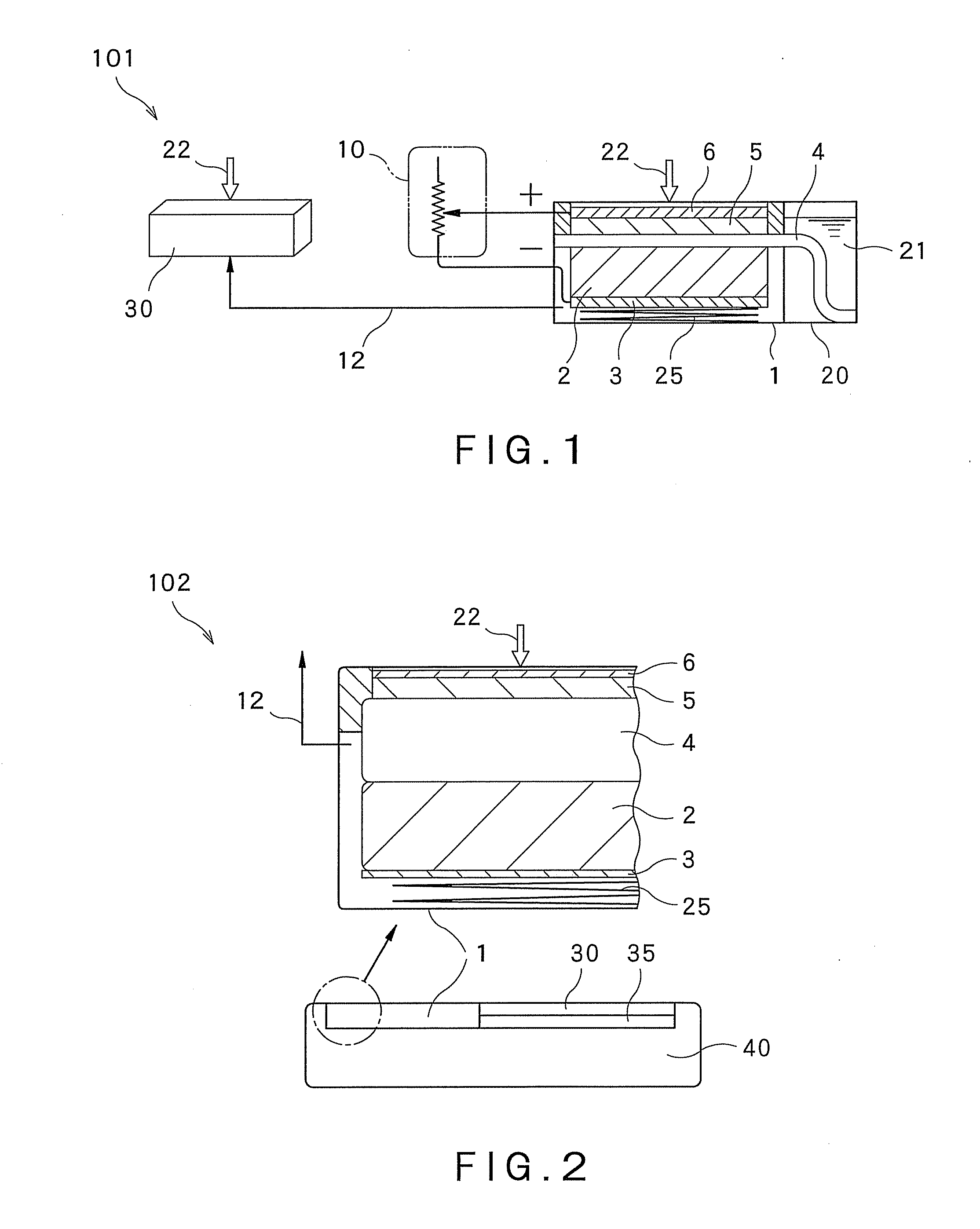
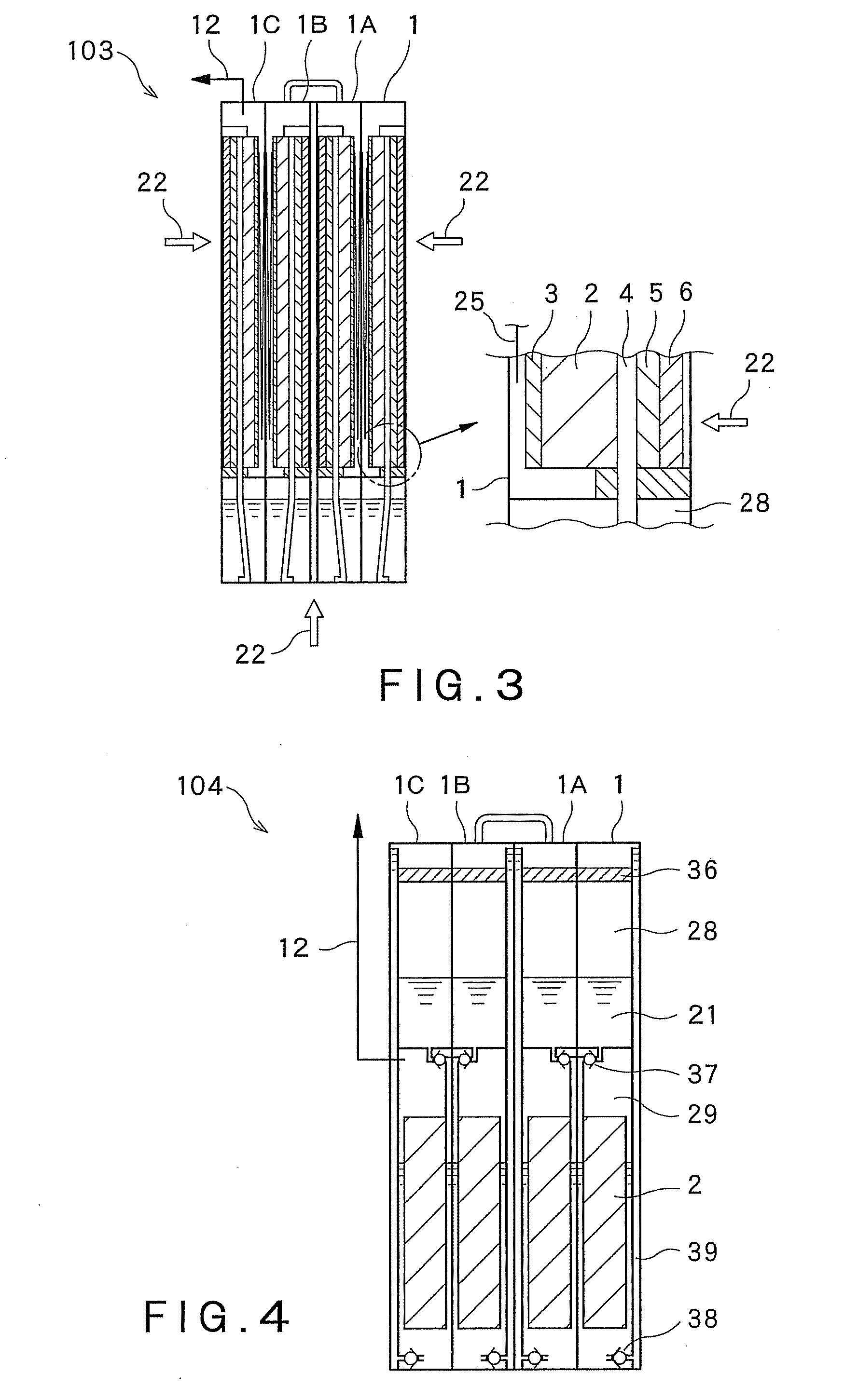
[0065]FIG. 2 shows an embodiment 102 that is a power supply unit which, in use, is usually carried. In this embodiment 102, a hydrogen generating container 1 is incorporated in a portable (cellular) phone 40. FIG. 3 shows an embodiment 103 which is a middle- to large-size apparatus in which the hydrogen generating containers 1 are stacked.

[0066]When the hydrogen generating c...


PUM

PropertyMeasurementUnit
particle sizeaaaaaaaaaa
temperatureaaaaaaaaaa

Abstract

This invention relates to a power generating apparatus including two systems. In one of the systems, a hydrogen gas is generated by hydrolysis, and a hydrogen demanding unit generates electric power. In the other system, electric power is generated based on an oxidation-reduction chemical reaction of an electrode and ions.

Description

FIELD OF INVENTION[0001]The present invention relates to a power generating apparatus including two systems one of which generates a hydrogen gas by hydrolysis and generates electric power by a hydrogen demanding unit and the other generates electric power by an oxidation-reduction chemical reaction involving electrodes and a plurality of ions.BACKGROUND ART[0002]Power generating apparatuses have been proposed in which hydrogen is generated by heating a metal material or the like at a high temperature to hydrolyze water, or by reacting a dry solid hydride with steam, is supplied to a fuel cell or the like and is reacted with oxygen to generate current.[0003]Such apparatuses are disclosed in the following documents.[Patent document 1] Japanese Patent Laid-Open No. 2004-149394[Patent document 2] Japanese Patent Laid-Open No. 2002-069558[Patent document 3] International Patent Publication WO2003 / 020635[0004]The generation of hydrogen by heating a metal material at a high temperature is...

Claims


Application Information

Patent Timeline
Patent Type & Authority Applications(United States)
IPC IPC(8): H01M8/16H01M4/02H01M4/58
CPCC01B3/065C01B3/08C01B2203/066Y02E60/50H01M8/0606H01M16/003Y02E60/362H01M8/04089Y02P20/129Y02E60/36H01M8/04
Inventor TSUJI, NOBUYOSHI
Owner TECH BANK CO LTD
Why Eureka
Try Eureka