Focused beam reflectance measurement to optimized desalter performance and reduce downstream fouling

a technology of focused beam and reflectance measurement, which is applied in the direction of solvent extraction, separation process, water treatment, etc., can solve the problems of low thermal conductivity of fouling layer, affecting equipment operation, and accumulation of unwanted fouling, so as to enhance desalter performance

Inactive Publication Date: 2010-02-18
GREANEY MARK A +3
View PDF4 Cites 12 Cited by
  • Summary
  • Abstract
  • Description
  • Claims
  • Application Information

AI Technical Summary

Benefits of technology

[0021]The invention is also directed to a desalter for use in a refining operation, comprising a raw crude oil input, a wash water input in fluid communication with the raw crude oil input, including a mixer that mixes the raw crude oil with the wash water, and a vessel in fluid communication with the raw crude oil input that receives the raw crude oil and wash water mixture and a desalting mechanism connected to the vessel that operates on the mixture to dissolve salts from the mixture, to separate solids, and to separate the crude oil from the water. The desalter further comprises a desalted crude oil output in fluid communication with the vessel for discharging desalted crude oil for processing, a waste water output in fluid communication with the vessel for discharging waste water, and at least one sensor connected to the output that measures particles and droplets in the desalted crude oil output and generates data based on the measurement. Other additives to enhance desalter performance such as coalescing and flocculation aids may also be added to either or both the water or crude oil during the desalting process.

Problems solved by technology

In petroleum processing, fouling is the accumulation of unwanted hydrocarbon-based deposits on heat exchanger surfaces.
It has been recognized as a nearly universal problem in design and operation of refining and petrochemical processing systems, and affects the operation of equipment in two ways.
First, the fouling layer has a low thermal conductivity.
This increases the resistance to heat transfer and reduces the effectiveness of the heat exchangers.
Second, as deposition occurs, the cross-sectional area is reduced, which causes an increase in pressure drop across the apparatus.
One source of fouling is carryover of brine and solids from a desalter, which will adversely affect downstream equipment.
The latter are known to contribute to fouling of crude preheat exchangers.
The impact of desalter upsets on downstream heat exchangers is a known problem.
The aqueous brine, which contains dissolved salts such as sodium chloride, when carried-over with the desalted oil leads to fouling in the crude preheat exchangers and can contribute to overhead corrosion in the pipestill itself.
Another source of fouling is asphaltene precipitation due to blending of incompatible crude oils.
Though guidelines are available to assist refinery operators to avoid this situation, it occurs nonetheless, with subsequent heat exchanger fouling.
Otherwise, foulant deposits reduce the heat transfer efficiency, which requires higher fuel consumption in downstream atmospheric pipestill furnaces.
However, due to the optical opacity of crude oil, these methods cannot be used.
Thus, in a refinery setting, these methods have a low level of reliability.

Method used


Image

  • Focused beam reflectance measurement to optimized desalter performance and reduce downstream fouling
  • Focused beam reflectance measurement to optimized desalter performance and reduce downstream fouling
  • Focused beam reflectance measurement to optimized desalter performance and reduce downstream fouling

Examples


experiment 1

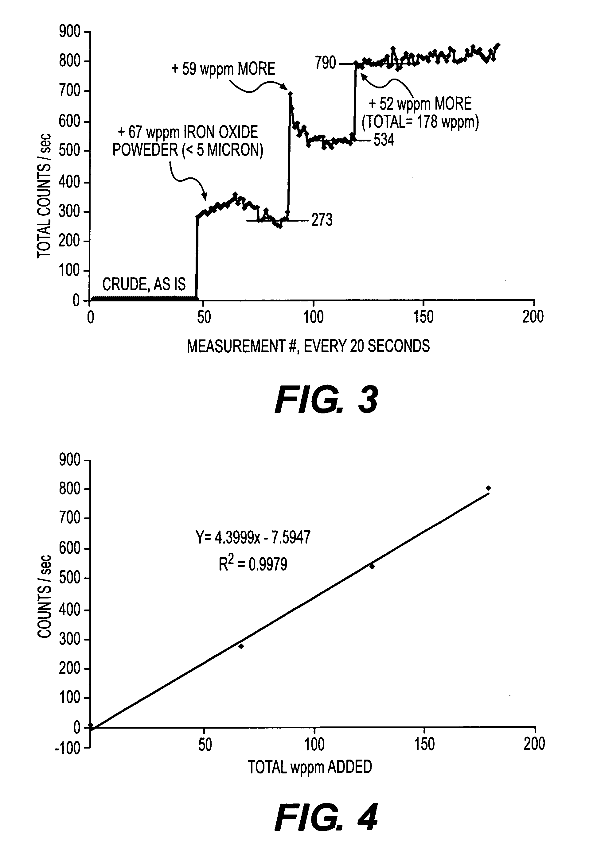
[0048]To demonstrate that fine solid particles at the 50 wppm concentration level in crude oil can be detected, an experiment using the Lasentec® FBRM® was used. Two hundred mls of whole crude oil was poured into a glass beaker. This beaker was then positioned in the Lasentec® fixed beaker stand that holds the Lasentec® probe in an optimal position within the beaker in relation to a variable speed, four blade propeller stirrer that circulates the test solution past the probe window. The measurements were conducted at ambient temperature. After an initial total particle count was obtained with the instrument, data collection was halted. Then, about 10 mgs of iron oxide powder (Aldrich, 2=0.998.

experiment 2

[0049]A second experiment was conducted to demonstrate that brine dispersed in crude oil can be detected. The experiment used the Lasentec® FBRM® with the same experimental set up and procedure as in the first experiment, described above, except that aliquots of a 20 weight % sodium chloride in water solution was added rather than the addition of aliquots of solid iron oxide. The first addition represented 0.1 volume %, and no change in total particle counts was recorded. For the FBRM®, “particles” can be solid particles, gas bubbles, or dispersed second liquid phases, such as brine droplets, as in this case. Upon addition of 1 volume % of brine, a significant jump in signal was observed. Additional increases of 2 volume % and 5 volume % also produced increases in particle counts, but not in a linear fashion, as in the first experiment. This may be due to the unstable nature of the dispersion that is produced by the addition of brine droplets, as brine droplets will coalesce with ea...

experiment 3

[0050]In a third experiment, the FBRM® probe was used to detect the formation of asphaltenes during the course of the blending of two incompatible crude oils. Initially, 250 mls of a crude oil was stirred at room temperature, and the probe was used to measure the background particle content. At room temperature, wax crystallites in the crude oil were evident by eye and produced a noisy baseline to the FBRM®, as seen in FIG. 6. After an addition of 150 mls of n-heptane, most of the wax crystals appeared to dissolve, and the total particle count dropped to a steady low level. Upon addition of 50 mls more of heptane, the particle count increased dramatically. Initially, this growth was limited to the smaller particles in the 0.8 and 5.5 micron chord length range. Then, the particles grew progressively larger. As indicated in FIG. 6, the Lasentec® FBRM® was used to detect the “titration-like” response at the point of asphaltene phase separation. The absence and presence of asphaltenes w...


PUM

PropertyMeasurementUnit
temperaturesaaaaaaaaaa
weight %aaaaaaaaaa
chord lengthaaaaaaaaaa

Abstract

Performance of equipment, such as a desalter, in a refinery is monitored in real-time and on-line to minimize fouling of downstream equipment. Using an instrument to measure particles and droplets in-process allows monitoring of the various operations to optimize performance. Such measurement can also be used during crude oil blending to detect asphaltene precipitates that can cause fouling and can be used for monitoring other fouling streams.

Description

BACKGROUND OF THE INVENTION[0001]1. Field of the Invention[0002]This invention relates to processing of whole crude oils, blends and fractions in refineries and petrochemical plants. In particular, this invention relates to monitoring performance of components in a refinery, especially monitoring performance of a desalter. This invention also relates to optimizing a refinery operation to mitigate fouling.[0003]2. Discussion of Related Art[0004]Fouling is generally defined as the accumulation of unwanted materials on the surfaces of processing equipment. In petroleum processing, fouling is the accumulation of unwanted hydrocarbon-based deposits on heat exchanger surfaces. These deposits often include inorganic materials as well. It has been recognized as a nearly universal problem in design and operation of refining and petrochemical processing systems, and affects the operation of equipment in two ways. First, the fouling layer has a low thermal conductivity. This increases the resi...

Claims


Application Information

Patent Timeline
Patent Type & Authority Applications(United States)
IPC IPC(8): C10G31/08C10G32/02B01D17/02
CPCB08B17/00C10G31/09C10G75/00C10G33/08C10G32/02
Inventor GREANEY, MARK A.BRONS, GLEN B.WRIGHT, CHRIS A.LETA, DANIEL P.
Owner GREANEY MARK A
Why Eureka
Try Eureka